Assembly for Deploying a Payload from a Submarine

a payload and submerged technology, applied in the field of submerged apparatus for deploying payloads, can solve the problems of cover breaking and the payload being forced through the opening,

Active Publication Date: 2009-05-21
BABCOCK IP MANAGEMENT NUMBER ONE LTD
View PDF8 Cites 17 Cited by
  • Summary
  • Abstract
  • Description
  • Claims
  • Application Information

AI Technical Summary

Benefits of technology

[0012]By being located in the pressure vessel, the payload can be maintained at an appropriate pressure, i.e. a pressure which does not cause it substantial damage, allowing it to be stored outside the submarine's pressure hull.
[0041]The simplicity of this arrangement, in which the assembly of the present invention may deploy a payload from both a submerged or surfaced submarine using the same procedure, is a key advantage of the first aspect of the present invention.

Problems solved by technology

Therefore, upon operation of the ram, the ram may force the payload against the releasable cover, causing the cover to break.
Thus, the cover may not prevent the payload from being forced through the opening.

Method used


Image

  • Assembly for Deploying a Payload from a Submarine
  • Assembly for Deploying a Payload from a Submarine
  • Assembly for Deploying a Payload from a Submarine

Examples


Embodiment Construction

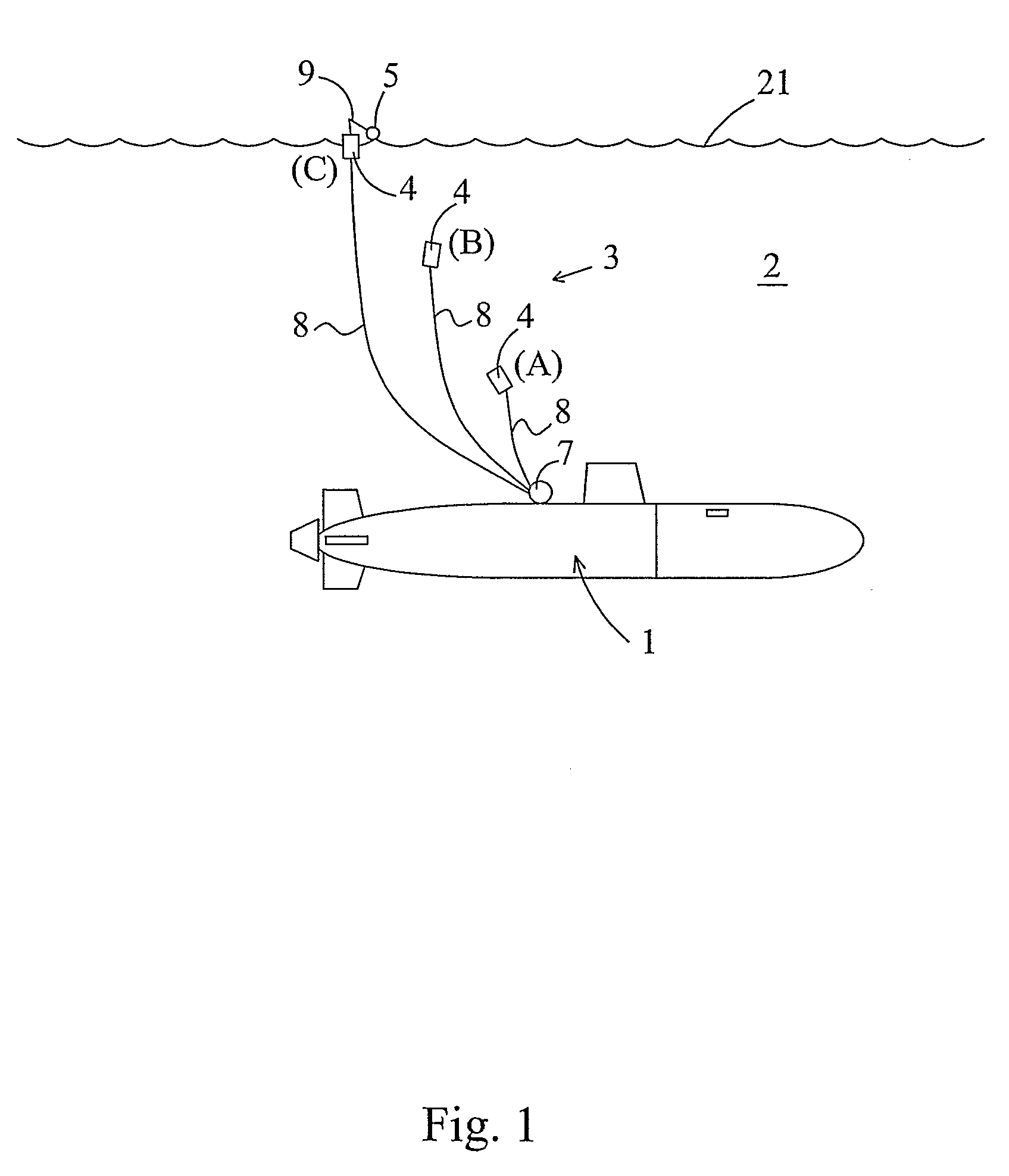
[0074]A submarine 1 according to the present invention is shown in FIG. 1, which is submerged in water 2 (e.g. the sea). The surface 21 of the water 2 is represented by a wavy line.

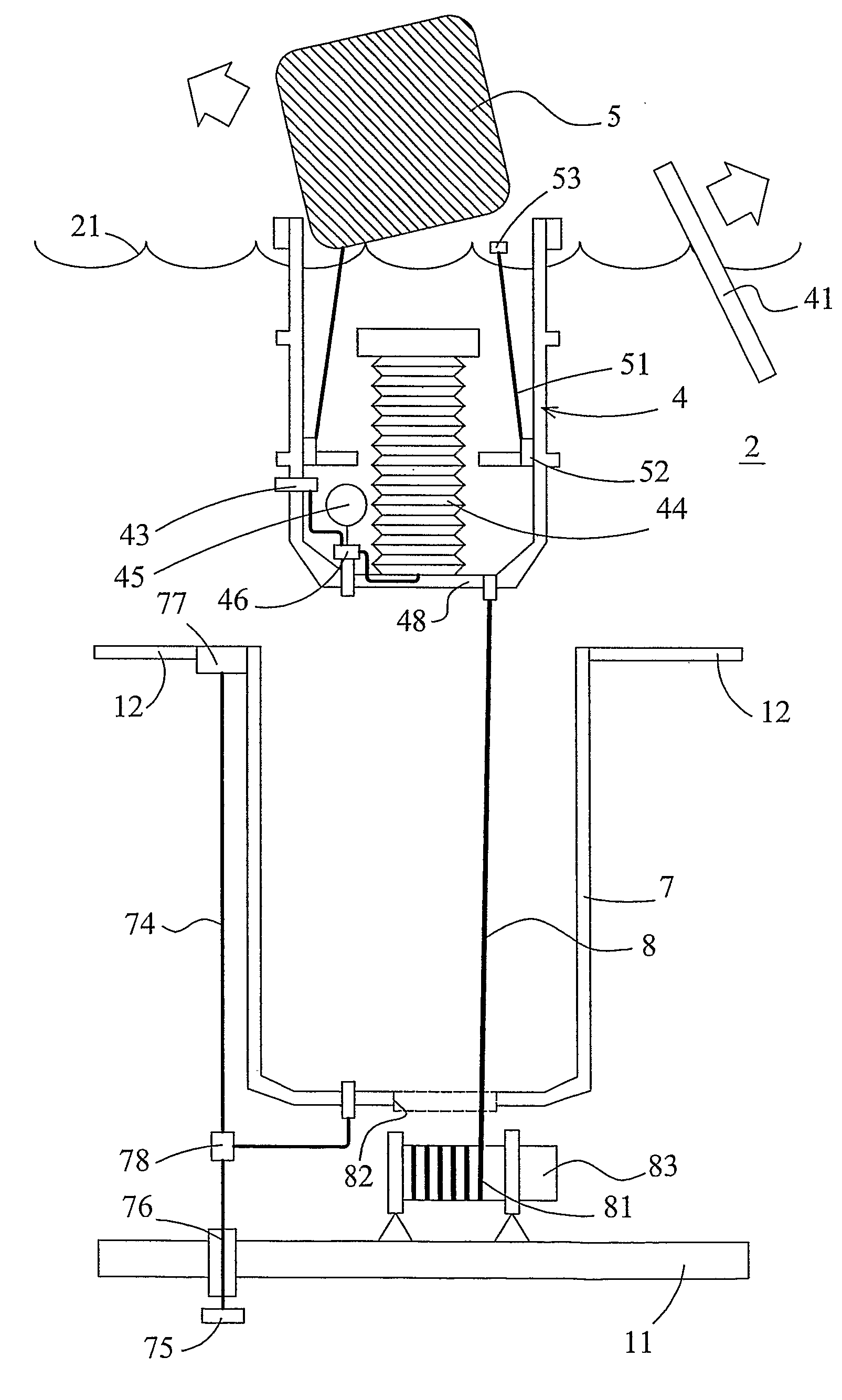
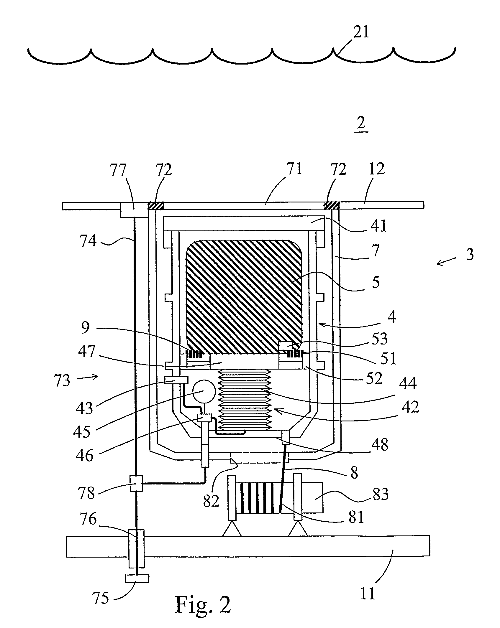
[0075]The submarine 1 is fitted with an assembly 3. This assembly 3 constitutes a life raft deployment system and includes a pressure vessel 4 and a containerised life raft 5. Before deployment, the life raft 5 is stored in the pressure vessel 4 at atmospheric pressure, and the pressure vessel 4 is stored in an enclosure, e.g. a well 7, situated at an upper region of the submarine, outside the submarine's main pressure hull 11. For simplicity, in FIG. 1, the well 7 is represented by a circle, protruding from the submarine 1. However, in reality, the well is e.g. located between the submarine's pressure hull 11 and the submarine's outer casing 12 as shown in FIGS. 2 to 4, FIGS. 5 to 7, and FIG. 8, providing there is sufficient space between the casing and the pressure hull to allow the system to be install...


PUM


Abstract

A submarine (1) has an assembly (3) for deploying a life raft (5), the assembly (3) being located in a well (7) formed outside the submarine's pressure hull (11). The assembly includes a pressure vessel (4) for storing the life raft (5) in a pressurized state. To deploy underwater, a lid (71) covering an opening to the well (7) is released to permit the assembly (3), which is buoyant, to ascend towards the water surface. A sensor (43) determines proximity to the water surface, whereby a pneumatic ram (42) in the pressure vessel is activated to eject the life raft (5) from the pressure vessel (4).

Description

BACKGROUND OF THE INVENTION[0001]1. Field of the Invention[0002]The field of this invention relates to apparatus for deploying payloads, e.g. life rafts, from submarines.[0003]2. Summary of the Prior Art[0004]Life rafts are known for use in submarines, and are provided for use in emergency situations, enabling safe abandonment of the submarines.[0005]Standard life rafts are not designed to survive pressures at deep submarine dive depths. Thus, life rafts are usually stored in the submarine's pressure hull, i.e. the main pressurised internal volume of the submarine. This means that the life rafts must be small enough to be carried by a person through an escape hatch of the submarine, and that valuable space in the submarine's pressure hull is consumed whilst they are stored ready for deployment.SUMMARY OF THE INVENTION[0006]According to a first aspect of the present invention, there may be provided:[0007]a submarine comprising an assembly for deploying a payload from the submarine, t...

Claims


Application Information

Patent Timeline
Patent Type & Authority Applications(United States)
IPC IPC(8): B63G8/41
CPCB63G8/41B63C9/22
Inventor WOOLWRIGHT, MICHAELMURPHY, CHRISDOBBIN, JAMES
Owner BABCOCK IP MANAGEMENT NUMBER ONE LTD
Why Eureka
Try Eureka