
Stone Saw Blade

a saw blade and stone technology, applied in the field of saw blades, can solve the problems of reducing the cutting power of stone-like materials, affecting the cutting effect, and affecting the cutting effect, and achieve the effect of preventing tooth wear and tear and great hardness

Inactive Publication Date: 2009-05-21
WIKUS SAGENFAB WILHELM H KULLMANN
View PDF18 Cites 28 Cited by
  • Summary
  • Abstract
  • Description
  • Claims
  • Application Information

AI Technical Summary

Benefits of technology

[0015]The novel layer is substantially harder than the carrier of the form body. The carrier is made of hard metal. The form bodies form the teeth of the saw blade, and they have a geometrically defined shape including a cutting portion, a cutting edge, a rake angle, a clearance angle, and so forth. It is sufficient if the layer being located on the form bodies being made of hard metal is comparatively thin. It is important that the layer has an extremely great hardness which is only achieved by few materials. Especially, the layer may be made of polycrystalline diamond (PCD) or cubic boron nitride (CBN). The use of such materials on saw blades is new, and it results in outstanding cutting results when sawing stone with the novel stone saw blade. For this purpose, the layer has a hardness of at least 5,000 HK (Knoop hardness). For low loads, the Knoop hardness approximately corresponds to the Vickers hardness (HK˜HV).
[0016]The layer may be arranged at the surface of the carrier of the form body facing towards the front as seen in the direction of movement of the saw blade during sawing. The layer forms a face at least partly being contacted by the material to be removed and the material which has already been removed. This also applies to the cutting edge of the face. The use of this layer having an extremely great hardness in combination with the design of the carrier leads to the desired effect when sawing stone that there rather is a beating or hammering action instead of a cutting removal of chips. During this beating or hammering action, small portions of the stone are smashed and shattered, and they are removed in this way. The layer also acts as a protective layer for the carrier of the form body and thus preventing wear and tear of the tooth.

Problems solved by technology

Such rope saws only supply low cutting power, they can only be operated with a comparatively small feed, and they produce a comparatively wide cutting channel in the stone such that there is a great loss of material during cutting.
The producible cuts are often not straight, and they are comparatively rough at the cutting surface.
Such known cutoff wheels supply advantageous cutting power, but they disadvantageously result in a respectively wide cutting channel being produced in the stone to be cut.
Drawbacks of such known frame saws are the low flexibility and the great thickness of the discs resulting from the design of the saw.

Method used


Image

  • Stone Saw Blade
  • Stone Saw Blade
  • Stone Saw Blade

Examples


Embodiment Construction

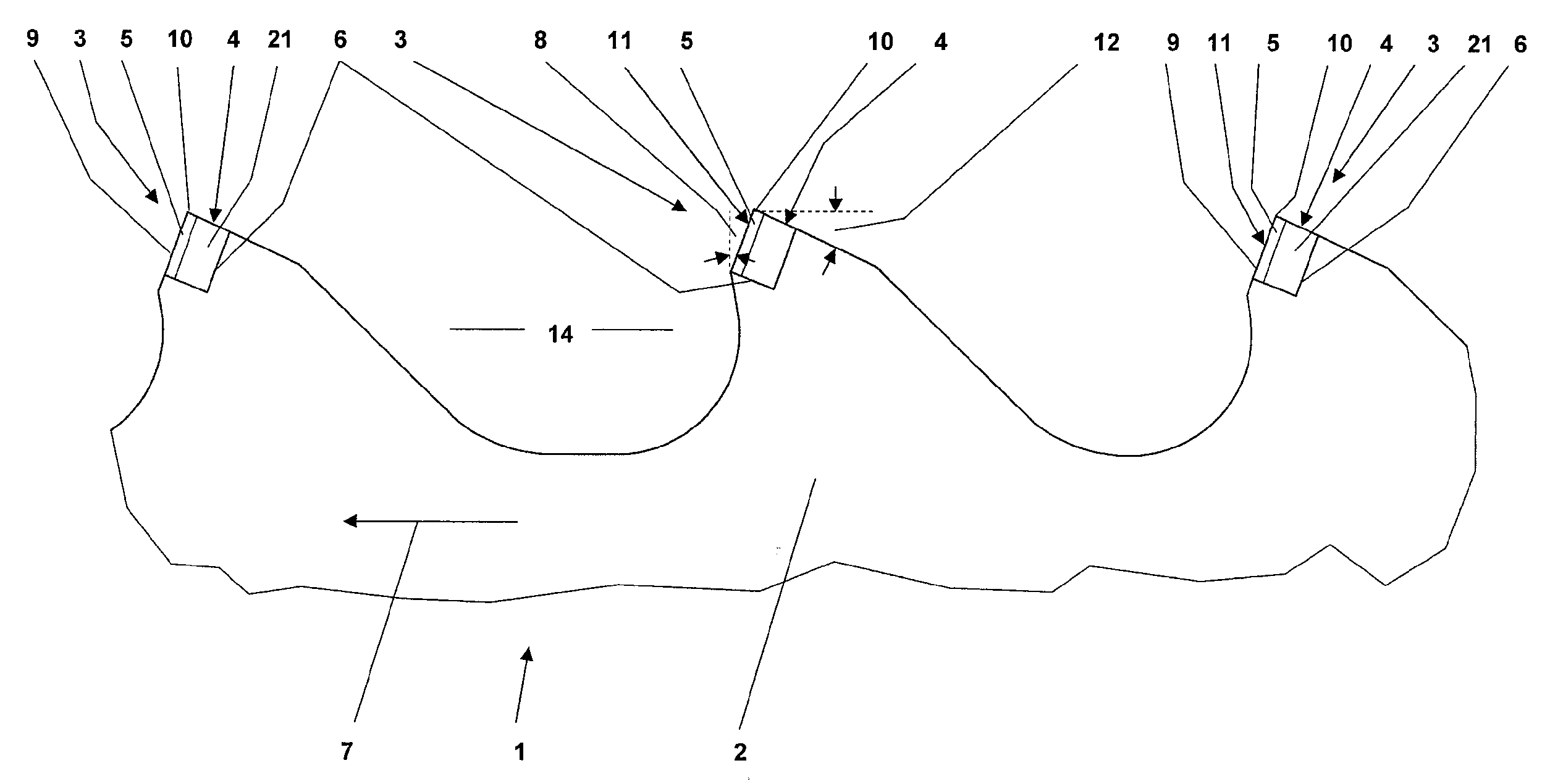
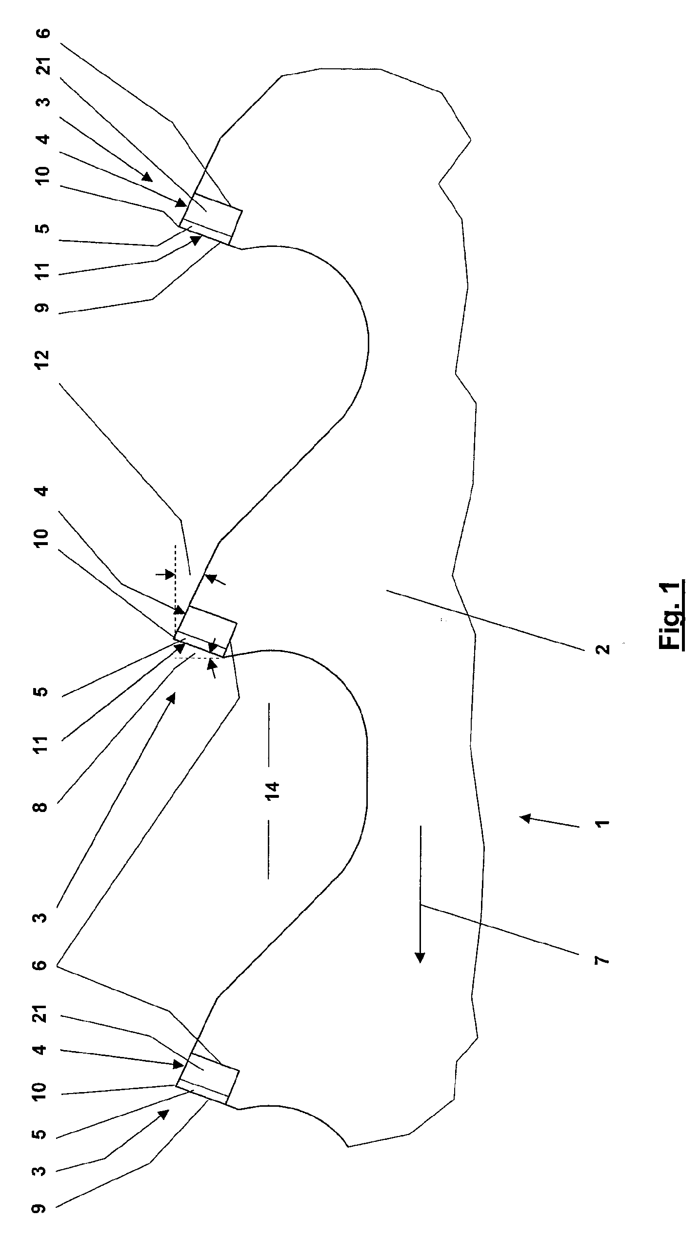
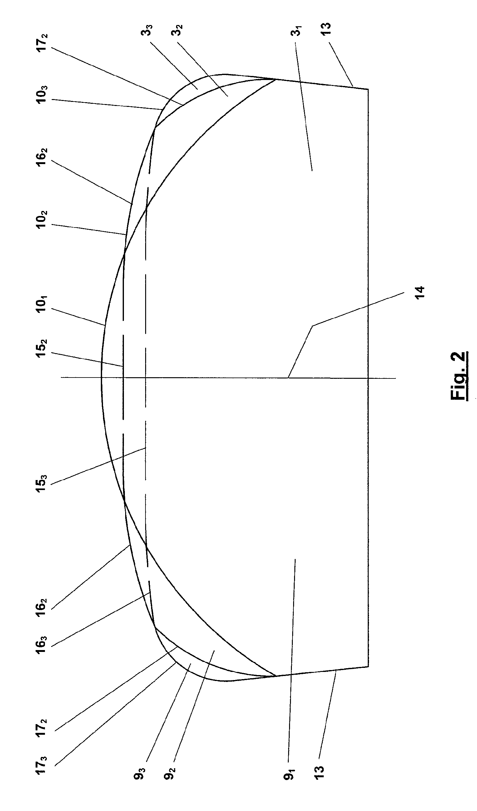
[0030]Referring now in greater detail to the drawings, FIG. 1 illustrates a side view of a first exemplary embodiment of a novel saw blade 1. The novel saw blade 1 is a stone saw blade 1. Only a part of the saw blade 1 is illustrated. The saw blade 1 includes an elongated base body 2 having a rectangular cross-section. The teeth 3 are arranged at one side of the base body 2. The teeth 3 are unset, and they are preferably designed and arranged to be symmetric with respect to the longitudinal center plane 14 of the base body 2. The teeth 3 have a width which is greater than the width of the base body 2.

[0031]The teeth 3 are partly formed by form bodies 4. Each form body 4 includes a carrier 21 being made of hard metal. Preferably, the greater part of the form body 4 is made of the carrier 21. At one side or surface, the form body 4 includes a layer 5 being made of a material which is even harder than the material of the carrier 21 of the form body 4, meaning harder than hard metal. Th...


PUM

PropertyMeasurementUnit
Angleaaaaaaaaaa
Angleaaaaaaaaaa
Angleaaaaaaaaaa

Abstract

A stone saw blade (1) includes an elongated base body (2) and a plurality of teeth (3). The teeth (3) are designed and arranged to be unset and to include geometrically defined cutting portions (11). The teeth (3) include a form body (4) being connected to the base body (2). The form body (4) includes a carrier (21) being made of hard metal and a layer (5) forming the cutting portion (11). The layer (5) has a hardness of at least 5,000 HK.

Description

CROSS REFERENCE TO RELATED APPLICATIONS[0001]This application claims priority to co-pending German Patent Application No. DE 10 2007 054 601.9 entitled “Sägeblatt mit einem Grundkörper und Zähnen mit Schneiden”, filed Nov. 15, 2007.FIELD OF THE INVENTION[0002]The present invention generally relates to a saw blade including an elongated base body and unset teeth having geometrically defined cutting portions. The teeth include form bodies being made of hard metal being connected to the base body.[0003]The saw blade is designed to have an elongated base body, meaning it is designed as a saw band. The elongated base body includes seats serving for arrangement of form bodies being made of hard metal. Usually, these seats are produced on the elongated base body by milling. The form bodies made of hard metal are manufactured as separate elements, and they are afterwards permanently connected to the elongated base body on the seats. The form bodies made of hard metal include cutting portion...

Claims


Application Information

Patent Timeline
IPC IPC(8): B28D1/08B28D1/12
CPCB23D61/121B28D1/127B23D61/14
Inventor KULLMANN, JORG H.KWANKA, WERNER
Owner WIKUS SAGENFAB WILHELM H KULLMANN
Learn More