
Semiconductor Structure and Method of Manufacturing a Semiconductor Structure

a semiconductor and semiconductor technology, applied in the field of semiconductor structure, can solve problems such as strain-induced dislocations in the structure formation, and achieve the effects of low diffusion region thickness, effective light diffusion capability, and convenient processing

Inactive Publication Date: 2009-05-21
OPTOGAN OY
View PDF12 Cites 3 Cited by
  • Summary
  • Abstract
  • Description
  • Claims
  • Application Information

AI Technical Summary

Benefits of technology

[0010]According to the present invention, said diffusion region comprises a plurality of diffusion layers, compositions and thicknesses of the diffusion layers having been chosen to avoid formation of strain-induced dislocations in the diffusion region. Preferably, each of the diffuse layers has non-flat surfaces in order to maximize the diffusion efficiency. Avoiding formation of dislocations is very important because dislocations could cause degradation of the properties of light emitting device layers later grown on the semiconductor structure. Avoiding dislocations can be realized by providing effective strain relaxation within the structure. In addition, in accordance of the present invention, the refractive index of adjacent diffusion layers are different in order to further enhance the diffusion efficiency via increased number of diffusing layer interfaces. The total thickness of the diffusion region is chosen to provide effective light diffusion. The bigger is the difference in refractive indices of the diffusion and cladding layers, the smaller is the required total diffusion region thickness. The structure of the present invention provides enhanced light diffusing capability resulting in highly increased brightness of a light emitting device grown on top of the structure without introducing additional dislocations in the layers. This is a great development step compared to the prior art substrates with light diffusion provided by insertion of a single diffusing layer.
[0012]In one preferred embodiment said bottom and top cladding layers are of the same material. In this case, the diffusion layers are preferably lattice matched to the cladding layers. Thus insertion of the diffusion region does not lead to generation of elastic misfit stresses in the layers, and no misfit dislocations are formed at the layer interfaces. Another alternative is that the diffusion layers are lattice mismatched to the bottom and the top cladding layers and thickness of each individual diffusion layer is smaller than the Matthews-Blakeslee critical thickness, which is the maximum thickness for a dislocation-free layer. Theory behind the Matthews-Blakeslee critical thickness will be explained later in this document. In addition, in this embodiment one of two adjacent diffusion layers has a positive and the other a negative lattice misfit to the cladding layers in order to avoid strain accumulation in the diffusion region. This feature together with said thickness limitation below the Matthews-Blakeslee critical thickness makes it possible to have a diffusion region with a sufficient thickness without additional strain-induced dislocations. For example, a stack consisting of pairs of first and second diffusion layers with equal thicknesses and having opposite lattice misfits of the same amplitude has a zero total strain.
[0013]In one special, preferred embodiment the bottom cladding layer and the diffuse layers have upper surfaces with facets having crystallographic indices other than (0001) and those of the type {1 100}. Thus the diffusion region reproduces the facets on the upper surface of the bottom cladding layer. This kind of structure having specific inclined facets results in effective light diffusion.
[0015]According to the present invention, the growing of the diffusion region comprises steps of growing a plurality of diffusion layers, compositions and thicknesses of the diffusion layers having been chosen to avoid formation of strain-induced dislocations in the layer interfaces, and adjacent diffusion layers having different refractive indices in order to further enhance the diffusion efficiency. Thus, the method of the present invention, in contrast to the methods disclosed in prior art utilizing insertion of a single diffusing layer, targets efficient light diffusion in the structure without introducing additional dislocations in the layers.
[0022]As a summary, several advantages in comparison to the prior art can be achieved with the present invention. A structure with effective light diffusion capability can be realized with a reasonable low diffusion region thickness and without causing harmful dislocations. The manufacturing process comprises in situ process steps only which makes the process very convenient and allows high production rate.

Problems solved by technology

Different lattice constants of the cladding layers could cause formation of strain-induced dislocations in the structure.

Method used


Image

  • Semiconductor Structure and Method of Manufacturing a Semiconductor Structure
  • Semiconductor Structure and Method of Manufacturing a Semiconductor Structure
  • Semiconductor Structure and Method of Manufacturing a Semiconductor Structure

Examples


Embodiment Construction

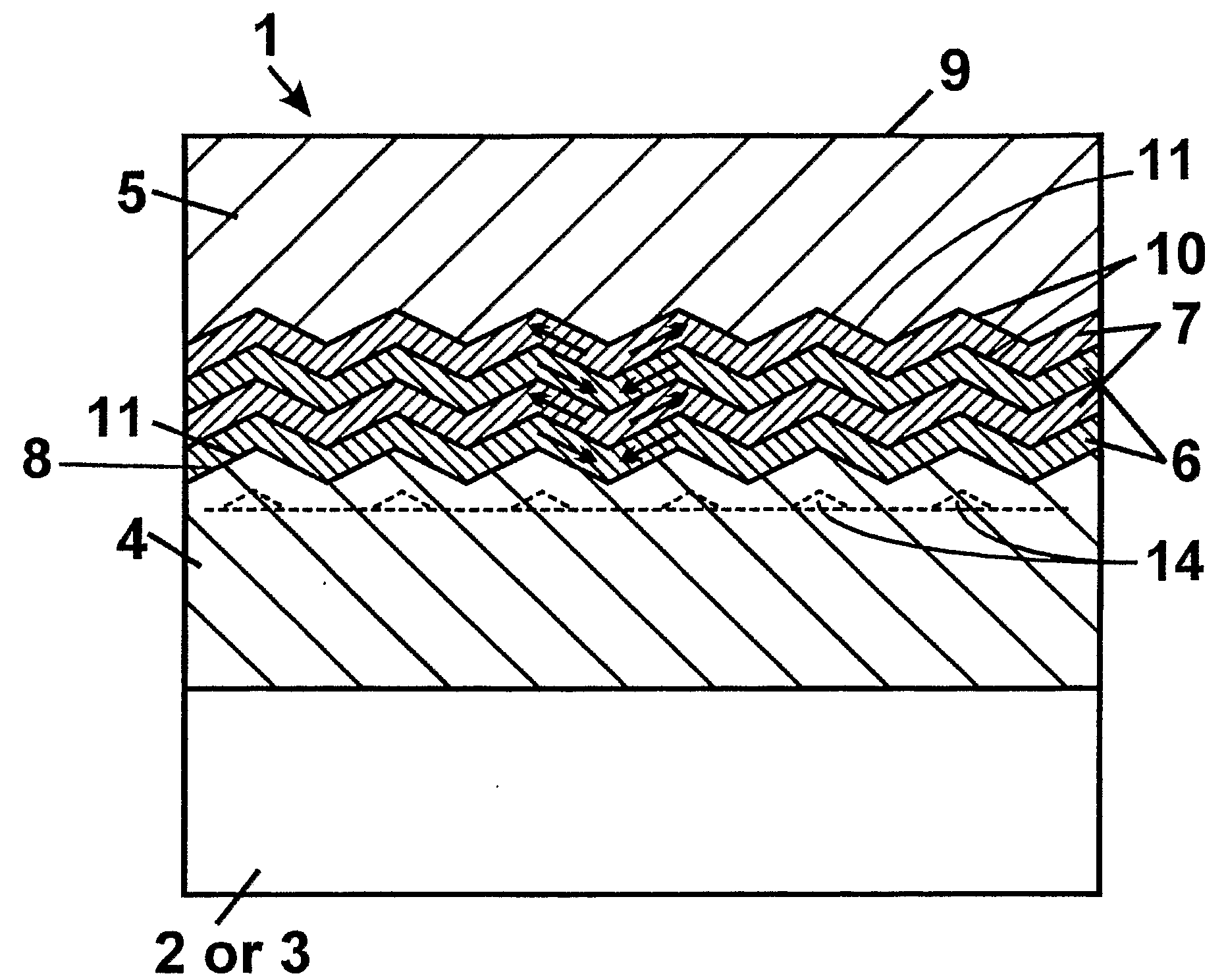
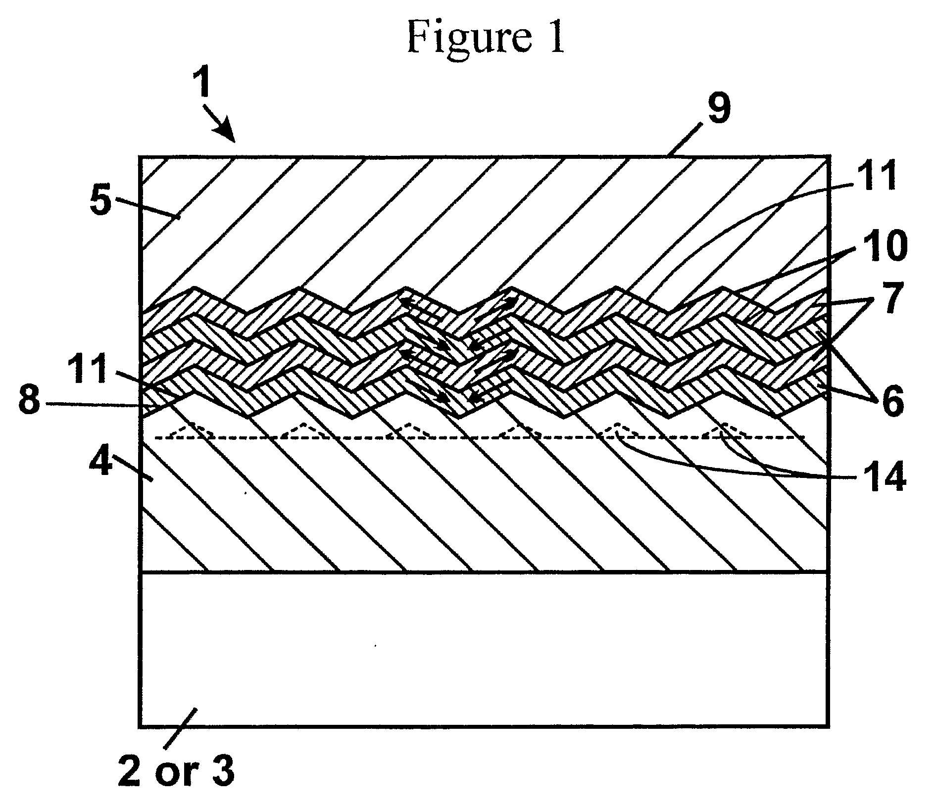
[0027]Reference will now be made in detail to the embodiments and examples relating to the present invention, which are illustrated in the accompanying figures.

[0028]The semiconductor structure 1 of FIG. 1 comprises a substrate 2 formed of the semiconductor structure materials or substrate 3 formed of foreign materials, a bottom cladding layer 4 with a surface 8 having facets 11 with crystallographic indexes other than (0001) and those of the type {1 100}, a top cladding layer 5 with flat surface 9, and a diffusion region consisting of two pairs of first diffusion layer 6 and second diffusion layer 7. Dashed line shows the precipitates 14 grown during the growing of the bottom cladding layer. The top cladding layer has a lattice constant equal to that of the bottom cladding layer. The diffusion layers have refractive indices different from those of the cladding layers. In addition, the refractive index of the first diffusion layers 6 is different from that of the second diffusion la...


PUM


Abstract

A semiconductor structure is formed of nitrides of group III metals having wurtzite crystal structure and grown in vapor phase on a (0001) oriented semiconductor substrate. The structure comprises a bottom cladding layer, a top cladding layer, and a diffusion region positioned between the cladding layers for diffusing light propagating within the semiconductor structure. The diffuse region has refractive index different from those of the cladding layers and non-flat surfaces for providing light diffusing interfaces between the diffusion region and the cladding layers. According to the invention, the diffusion region comprises a plurality of diffusion layers, compositions and thicknesses of said diffusion layers having been chosen to avoid formation of strain-induced dislocations in the diffusion region, and adjacent diffusion layers having different refractive indices in order to further enhance the diffusion efficiency.

Description

FIELD OF THE INVENTION[0001]The invention relates in general to a semiconductor structure with enhanced light diffusion capability to be used as a part of a light emitting device. More particularly, the semiconductor structure is formed of nitrides of group III metals with wurtzite crystal structure and grown in vapor phase on a (0001) oriented substrate, formed either of the semiconductor structure materials or of foreign materials. The invention also relates to a method of manufacturing such structure.BACKGROUND OF THE INVENTION[0002]Design of a semiconductor structure for light emitting diodes influences on overall efficiency of the diodes through two main parameters: efficiency of conversion of electrical power to optical power in light generation region and efficiency of emission of light generated in this region from the structure. In a light emitting structure made of nitrides of group III metals grown in vapor phase on foreign substrate with refractive index less than that o...

Claims


Application Information

Patent Timeline
Patent Type & Authority Applications(United States)
IPC IPC(8): H01L21/02H01L33/00H01L33/24
CPCH01L33/007H01L33/32H01L33/20H01L33/24
Inventor BOUGROV, VLADISLAV E.ODNOBLYUDOV, MAXIM A.
Owner OPTOGAN OY
Learn More