Insulating bobbin for stator of rotary machine
a technology of rotary machines and bobbins, which is applied in the direction of windings, electrical apparatus, dynamo-electric machines, etc., can solve the problems of not radiating heat generated by stator windings, and achieve the effect of reducing the possibility of space being caused by “wound expansion”, reducing the thickness of the corner section, and suppressing the reaction of the stator windings
- Summary
- Abstract
- Description
- Claims
- Application Information
AI Technical Summary
Benefits of technology
Problems solved by technology
Method used
Image
Examples
first embodiment
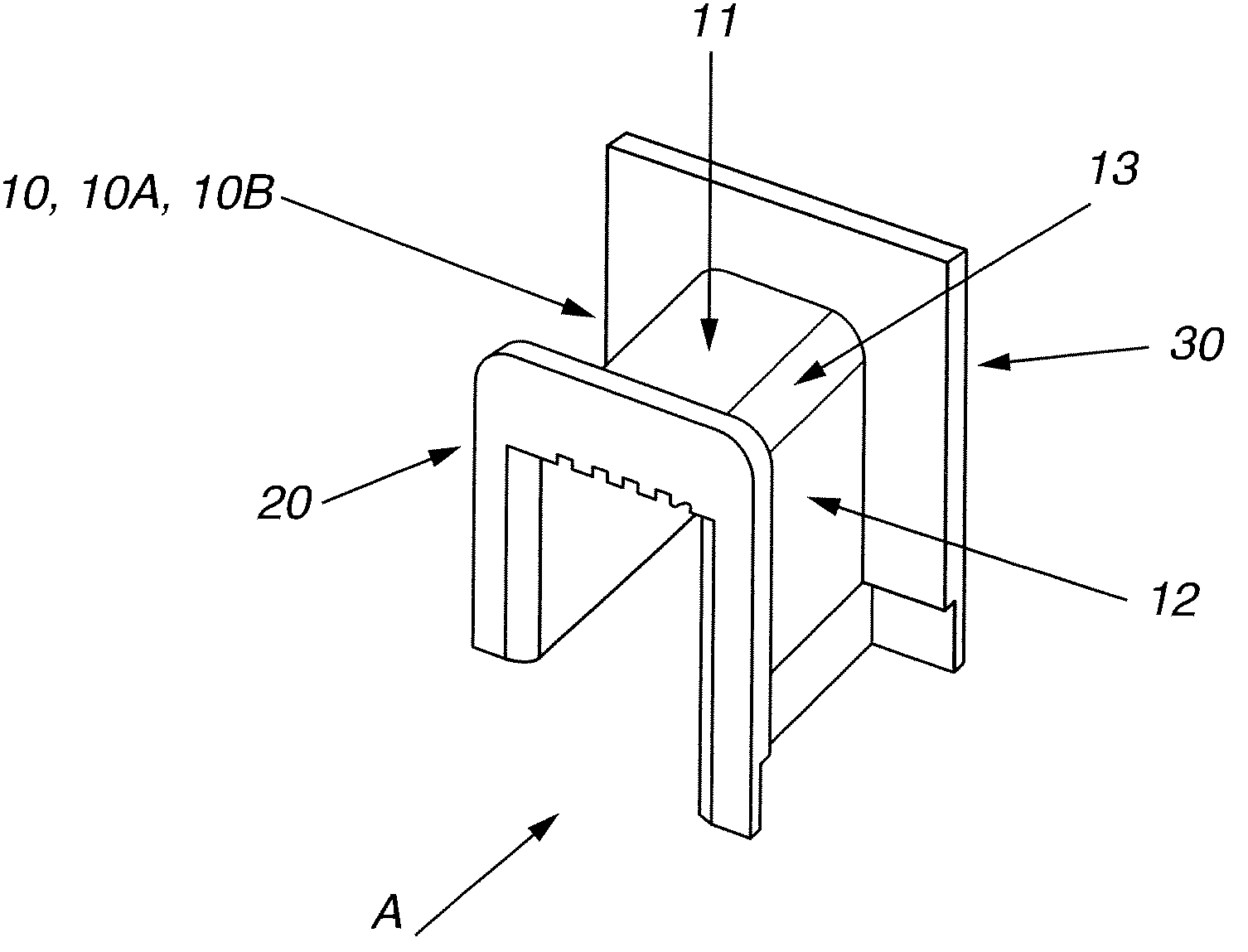
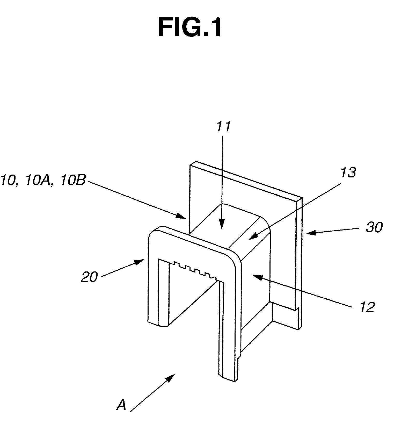
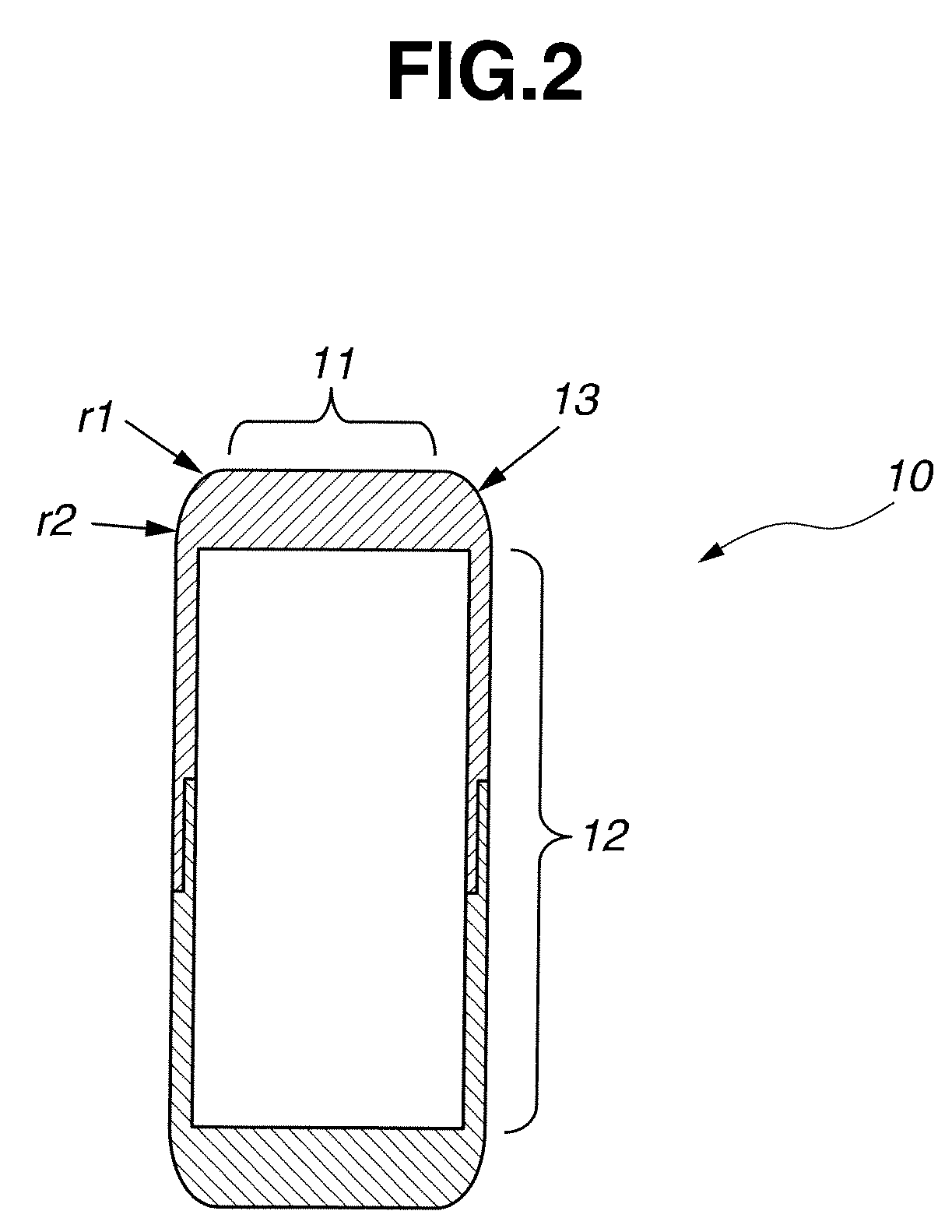
[0028]Firstly, the insulating bobbin according to the first embodiment of the present invention will be described with reference to FIG. 2. FIG. 2 is a sectional view of the insulating bobbin of the first embodiment, which is taken along a plane perpendicular to the direction of arrow A of FIG. 1.
[0029]In this embodiment, as shown in FIG. 2, the corner section 13 of the coil wound portion 10 is not rounded to have a single circular arc shape when viewed in cross section as in a prior art structure but to have a curved surface shape that is obtained by smoothly connecting a plurality of circular arcs (at least two circular arcs) that are arranged so that the radii of the circular arcs vary stepwise from the coil end section 11 on the upper side to the slot side section 12 on the lateral side sequentially, i.e., the corner section 13 is rounded to have a curved surface shape which is composed of a plurality of curved surface portions of different radius of curvatures. For example, the...
second embodiment
[0040]Then, the insulating bobbin according to the second embodiment of the present invention will be described with reference to FIG. 6. FIG. 6 is a sectional view of the insulating bobbin of the second embodiment, which is taken along a plane perpendicular to the direction of the arrow A of FIG. 1.
[0041]Even with the insulating bobbin of the first embodiment having been described with reference to FIG. 2, in which the corner section 13 is rounded to have, when viewed in cross section, a curved surface shape consisting of a plurality of circular arcs of radii that are varied stepwise from the upper coil end section 11 at the upper side to the slot side section 12 at the lateral side, there is a possibility that a quite small space due to “wound expansion” is caused as seen from the test result of FIG. 4 (in case of the example in which two circular arcs of radii of 2 mm and 9 mm are used, there is caused a space 40 (refer to FIG. 4) which is 0.28 mm in maximum, so that there may st...
third embodiment
[0055]Then, the insulating bobbin according to the third embodiment of this invention will be described with reference to FIG. 9. FIG. 9 is a sectional view of the insulating bobbin of the third embodiment, which is taken along a plane perpendicular to the direction of the arrow A of FIG. 1.
[0056]This embodiment is concerned with modified corner sections that are different in shape from the corner sections 13 of the first embodiment and modified thickened wall sections that are different in shape from the thickened wall sections 11a, 11b and the thickened wall sections 12a, 12b. Namely, in this embodiment, the corner section 13A is rounded to have a part-elliptic cross sectional shape corresponding to a curved surface shape obtained by varying the radii of a plurality of circular arcs continuously, and the ratio between the long axis and short axis of the ellipse is determined to be in a predetermined range. Further, the curved surface shapes of the coil end sections 11 and the slot...
PUM
 Abstract
Description
Claims
Application Information
 - R&D
- Intellectual Property
- Life Sciences
- Materials
- Tech Scout
- Unparalleled Data Quality
- Higher Quality Content
- 60% Fewer Hallucinations
Browse by: Latest US Patents, China's latest patents, Technical Efficacy Thesaurus, Application Domain, Technology Topic, Popular Technical Reports.
© 2025 PatSnap. All rights reserved.Legal|Privacy policy|Modern Slavery Act Transparency Statement|Sitemap|About US| Contact US: help@patsnap.com


