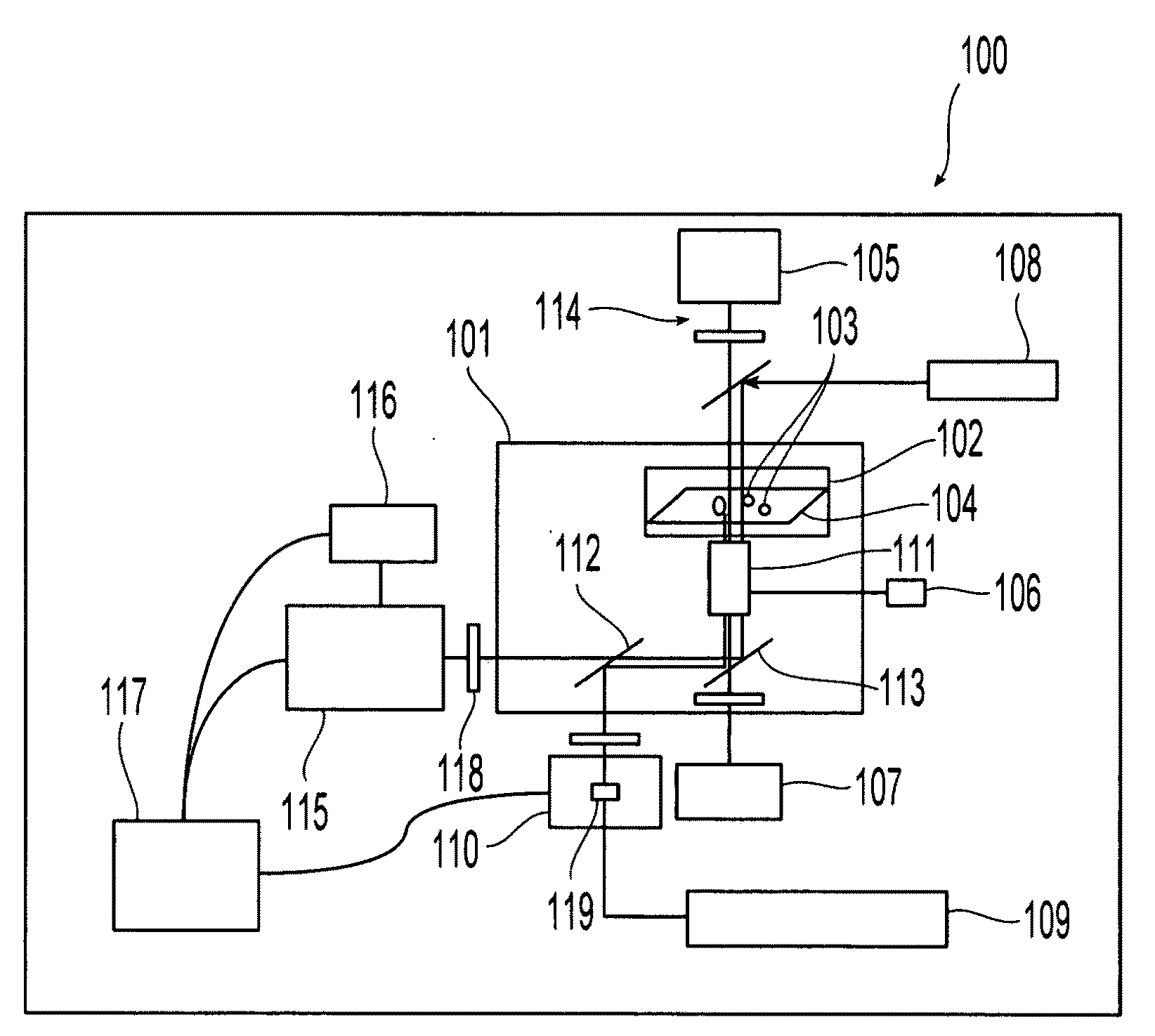
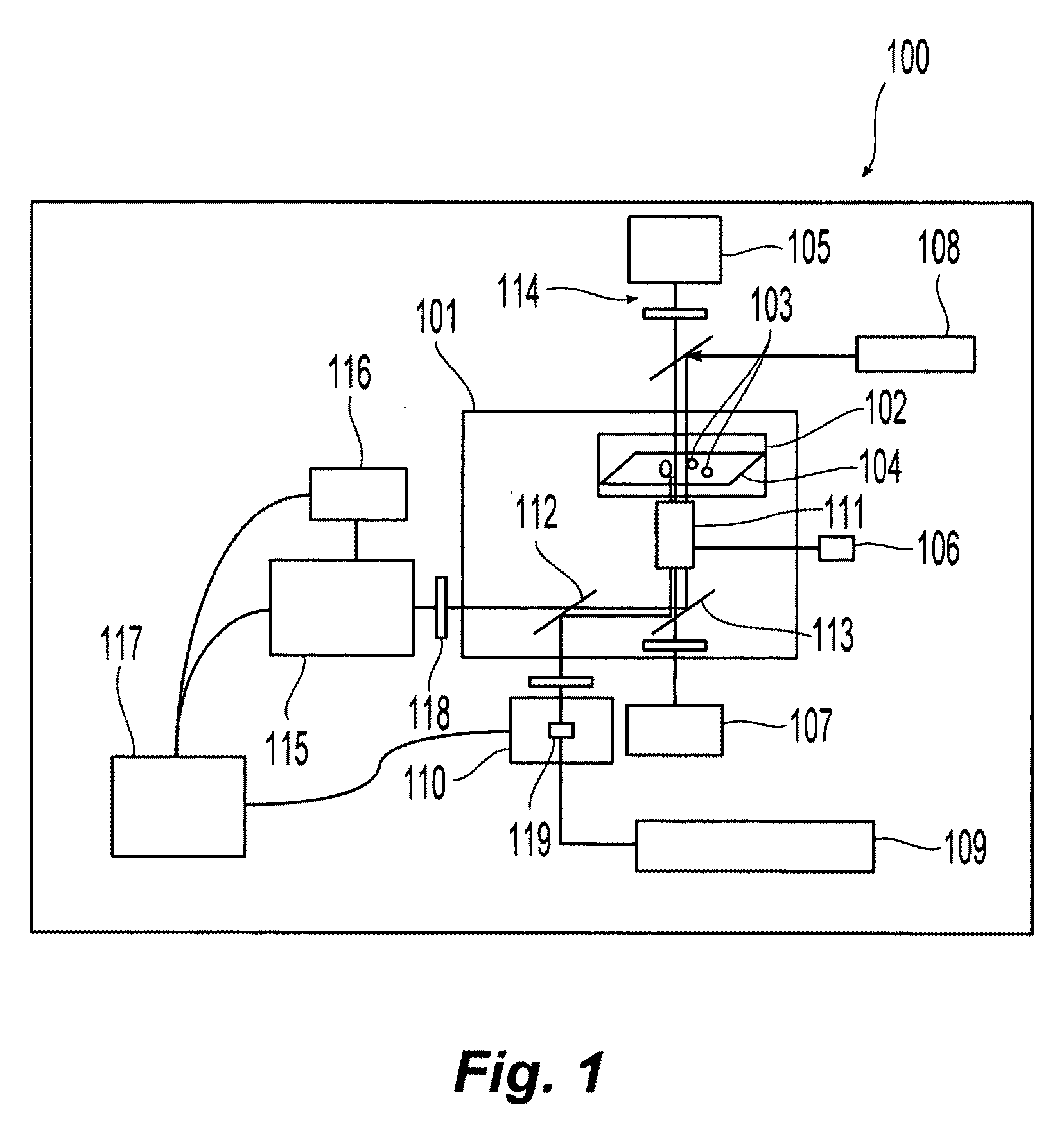
[0009]Thus, with the present invention, optical deformability of any type of
cell may be measured on the spatially modulated
optical force microscope (SMOFM), so that diseased cells, including
cancer cells, that have a unique optical deformability signature may be identified. In addition to being used as a diagnostic tool, the spatial light modulated force
microscope may also be used as an investigative tool to understand the causes of any change in optical deformability due to a particular diseased
cell state. Optical deformability of such cells may be correlated with
structural protein expression levels and patterns, for example, allowing the spatially modulated force
microscope to uncover the molecular origins for the changes in the viscoelastic responses of cells brought on by
disease.
[0010]The apparatus of the present invention is optically based, so it has the advantages of being a quick and sterile measurement platform. In contrast to the prior art, the objects or cells to be probed in the present invention may be adhering to a surface (i.e., microscope
cover slip surface), and so are able to retain their naturally present focal adhesions and stress fibers.
[0011]The present detection technique (using spatially modulated optical
microscopy) is a much more sensitive technique for the detection of deformation, with sub-nanometer level sensitivity, compared to that of prior art methods. The greater sensitivity of the present invention has two important advantages: 1) a greater
dynamic range of elastic responses may be probed, and 2) detectable deformations may be achieved at lower
laser powers. The second
advantage is an important consideration for parallelization.
[0013]In this way the
optical force microscopy apparatus of the present invention is a valuable tool for correlating molecular and genetic patterns in cells with a mechanical measurement of deformability, adding a new dimension to the characterization of cancerous phenotypes. The present invention also provides a basis for a
cancer screening assay based on a deformability measurement parameter.
[0015]In yet another embodiment consistent with the present invention, and based on the same principles as in the previous
Fourier Phase embodiment, a
modified technique for quantitatively measuring the
optical path length as opposed to using the above-identified
Fourier Phase technique, is a method called phase-stepped
holography, which allows the phase profile of an object or cell to be measured using only one image. In holographic phase-stepped
interferometry, a mutually coherent
reference beam and an object beam interfere, generating an interference pattern is at the
detector. However, in this embodiment, a
holographic optical element and transfer lens, are inserted between the object beam and a
beam splitter, and which diffracts the beam into several beamlets after passing through the sample, and before being directed by the
beam splitter into the
detector. The
holographic optical element splits the beam and makes replicas of the beam in space (i.e., phase-stepping the image in space)—in contradistinction to phase shifts in time, as is performed in the
Fourier phase microscopy component of the technique disclosed above. Thus, the phase-delayed or phase-stepped replicas of the image of the objects are diffracted into
four quadrants of the
detector, and simultaneously interfered with the
reference beam. A computer computes the phase profile of the objects from the four holographically phase-stepped replica images interfered with the
reference beam. Thus, this embodiment provides the
advantage that only one image is used to capture all four
phase shifted images, and thus allowing the phase profile of an object to be measured using only one image—which provides greater speed and efficiency. The measurement of the phase profile and the
optical path lengths is the same as discussed above in the
Fourier phase microscopy method.
[0018]Thus, the present invention is a valuable tool for correlating molecular and genetic patterns in cells which show a mechanical measurement of deformability, adding a new dimension to the characterization of cancerous phenotypes. The present invention also provides a basis for a
cancer screening assay based on a deformability measurement parameter.


