Multi-functional Mixer

Inactive Publication Date: 2009-05-21
TSANN KUEN CHINA ENTERPRISE
11 Cites 10 Cited by

AI-Extracted Technical Summary

Problems solved by technology

The abovementioned milk shaker/milk frother has only single function, so when it needs to make the milk shake and the milk frothing, the two aforementioned devices must be used, this i...

Benefits of technology

[0005]The major object of the present invention is to provide a multi-functional mixer which obviates the disadva...

Abstract

A multi-functional mixer comprises a housing, the housing having a containing space in which a container is placed; a motor device mounted on the housing; a stirring device connected to the motor device, wherein the stirring device comprises a stirring body and a frothing body driven by the motor and can mix the materials contained in the container. The multi-functional mixer of the present invention can be used for making milk shake and making milk frothing, which offers not only convenience, but also cost saving in making milk shake and milk frothing. The mixer has a steam function as well and can blow steam into the milk shake or the milk frothing, which steam flow can be adjusted through a steam control knob, which can control the temperature of the milk shake or milk frothing, and help frothing formation.

Application Domain

Rotary stirring mixersTransportation and packaging +3

Technology Topic

Cost savingsEngineering +2

Image

  • Multi-functional Mixer
  • Multi-functional Mixer
  • Multi-functional Mixer

Examples

  • Experimental program(1)

Example

[0015]FIG. 1 is a perspective view of the present invention used in making milk shake.
[0016]FIG. 2 is a perspective view of the present invention used in making milk frothing.
[0017]FIG. 3 is an exploded view of the present invention.
[0018]FIG. 4 is a perspective view of the members for making milk shake of the present invention.
[0019]FIG. 5 is a perspective view of the members for making milk frothing of the present invention.
[0020]FIG. 6 is an assembly view of the steam pipe of the present invention.
[0021]FIG. 7 is another perspective view of the members for making milk frothing of the present invention.
DETAILED DESCRIPTION OF THE PREFERRED EMBODIMENT
[0022]Preferred embodiments of the present invention will be described in detail with reference to the drawings and examples.
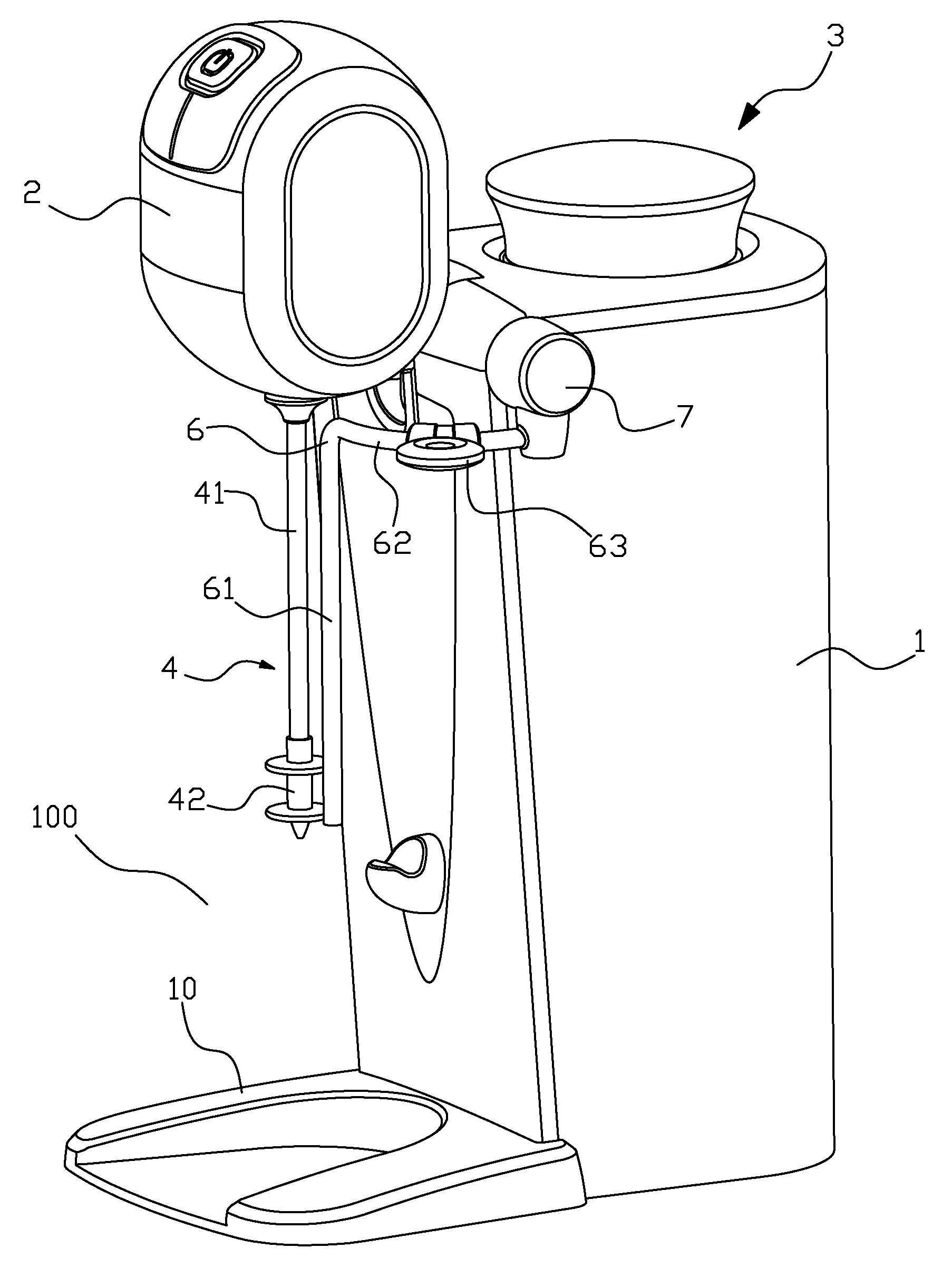
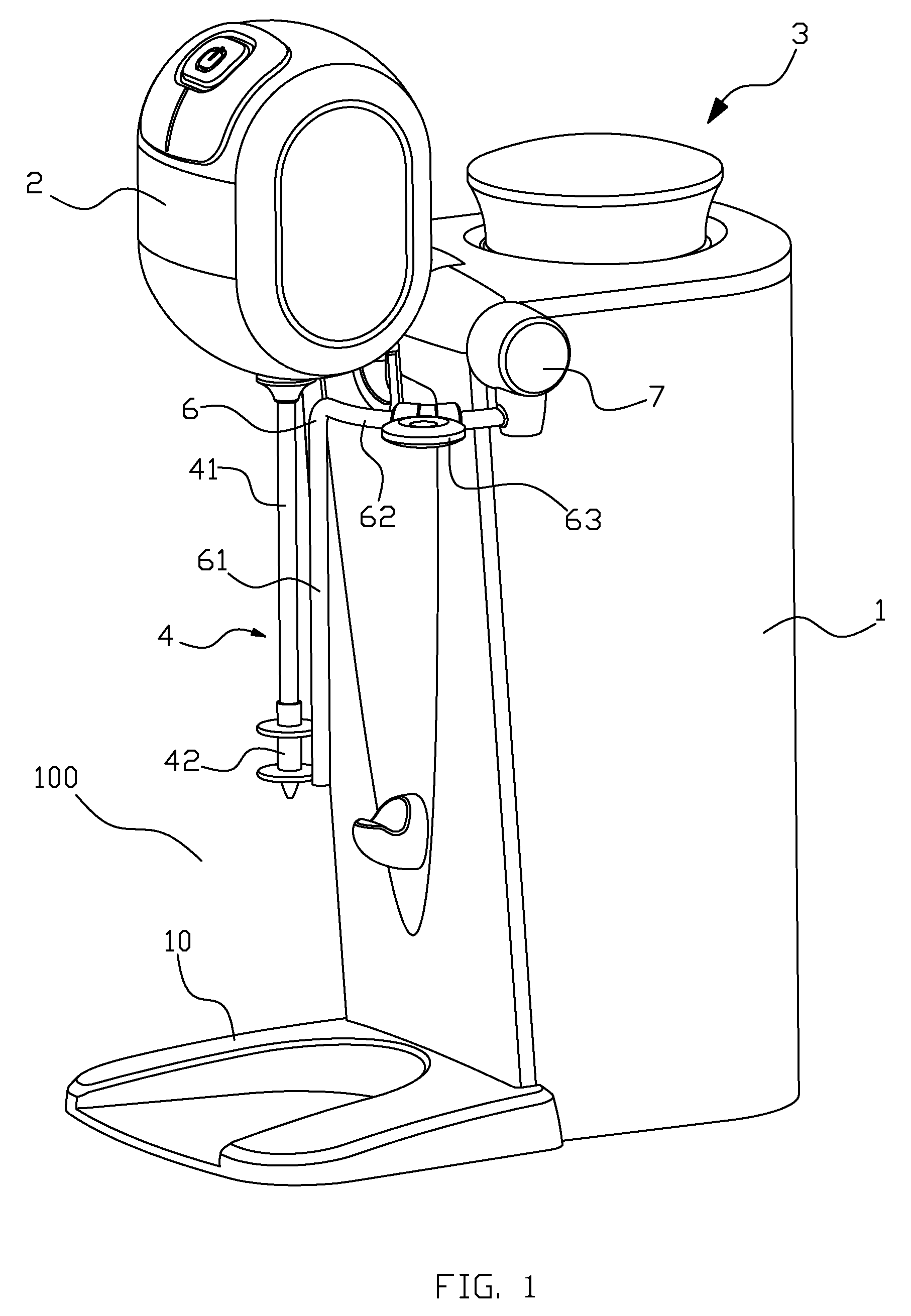
[0023]Referring to FIG. 1 and FIG. 2, the multi-functional mixer provided in the present invention for making milk shake, milk frothing or hot cocoa drinks etc. comprises a housing 1, the lower portion of the front of the housing 1 connected to a base 10, the base 10 formed a space 100 for containing a container 9, the container 9 is shown in FIG. 3.
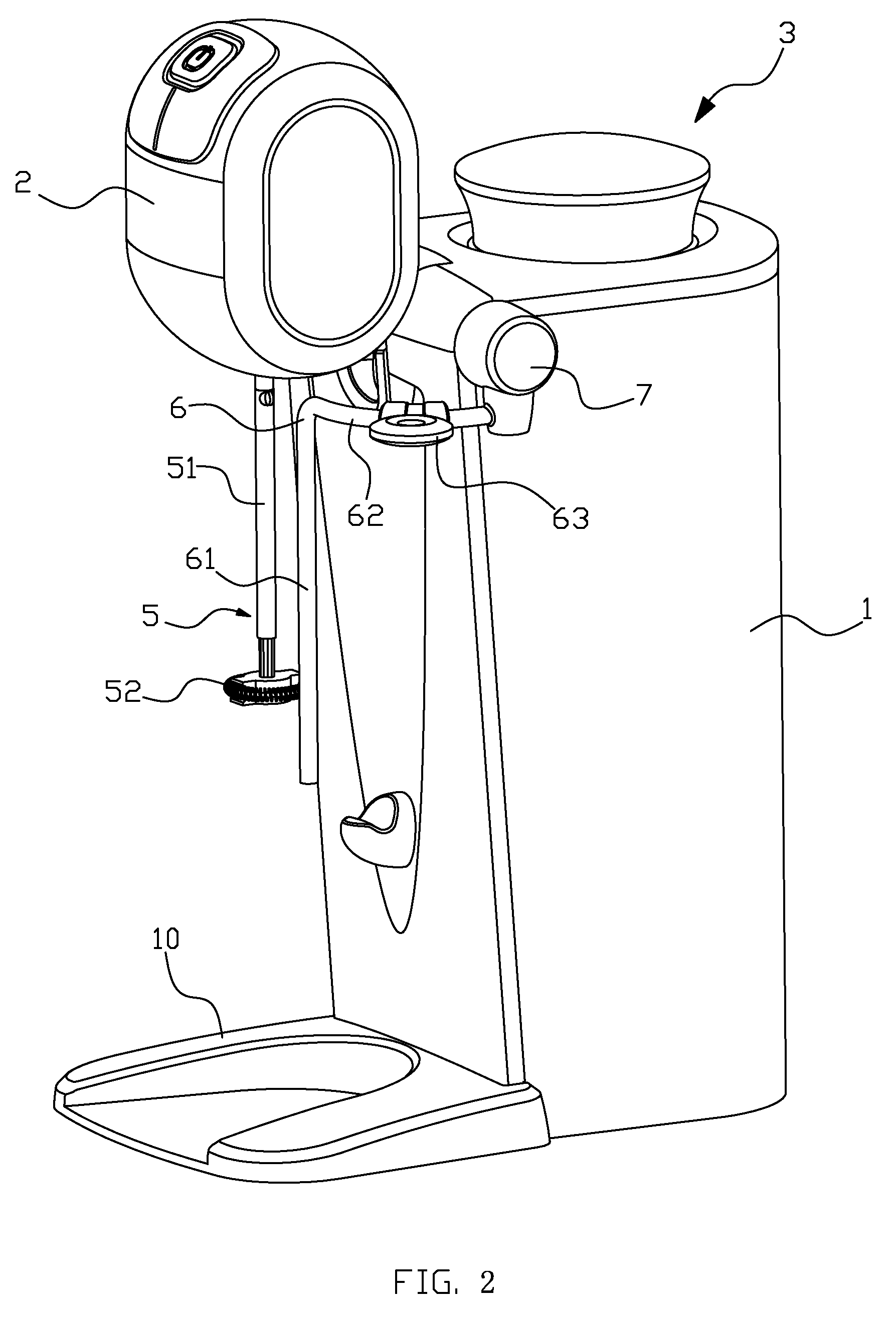
[0024]Referring to FIG. 1, the housing 1 has a motor device 2 and a stirring device connected to the motor device 2, in this embodiment, the stirring device comprises the interchangeable stirring members 4 and frothing members 5 for making milk shake and milk frothing respectively. By the interchange of the stirring members 4 and frothing members 5, the present mixer can perform the functions of making milk shake and milk frothing.
[0025]Referring to FIG. 3, the motor device 2 comprises a shell and a motor 21 enclosed in the shell. The shell includes a butt-jointed front shell 22 and a rear shell 23, and decorating circlets 24, 25 nesting in the left and right sides of the front shell 22 and the rear shell 23; the upper-front of the front shell 22 mounted a control panel 28 for controlling the motor; the output shaft of the motor 21 extends downwardly, the top and the bottom of the motor 21 mounted anti-vibration pads 26, 27 respectively. The shell pivotally connected to the upper portion of the front of the housing 1 swingable to the vertical direction via a hinged protruding portion 29 in the lower portion of the rear of the rear shell 23. The space 100 for containing container 9 formed between the shell and the base 10.
[0026]Referring to FIG. 1, FIG. 3 and FIG. 4, aforementioned stirring members comprise a stirring shaft 41 detachably connected to the output shaft of the motor 21 and a stirring body 42 connected to the lower end of the stirring shaft 41. The stirring body includes a sleeve 421 sheathing on the lower end of the stirring shaft 41 and two stirring rings 422, 423 integrative formed in the periphery wall of the sleeve 421 and extending out. When the stirring shaft 41 rotated, the stirring body 42 can make milk shake.
[0027]Referring to FIG. 2 and FIG. 5, the said frothing members 5 comprises a frothing shaft 51 detachably connected to the output shaft of the motor 21 and is interchangeable with the stirring shaft 4, and comprises a frothing body 52 connected to the lower end of the frothing shaft. The frothing body 52 include a bracket 521 and a frothing spring 522, the said bracket 521 sheathing on the lower end of the said frothing shaft 51, the two sides of the bracket 521 mounted slots 5211, 5212, the said frothing spring 522 is annular, and ringed in the slots 5211 and 5212, i.e. the centerline of the frothing spring is a ring, and the plane of the ring is vertical to the frothing shaft 51. When the frothing shaft 51 rotated, the frothing body 52 can make milk frothing. It should be noted that either one of the stirring shaft 41 or the frothing shaft 51 can be used as a driving shaft to connect either one of the stirring body 42 or the frothing body 52 to make beverages.
[0028]Referring to FIG. 3, the housing 1 comprises an enclosure wall 11, a top board 12 and a bottom board 13, the enclosure wall 11 formed the left, right and rear side walls of the housing 1, the top board 12 formed the top wall and front wall of the housing 1, the bottom board 13 formed the bottom wall of the housing 1. Referring to FIG. 1, FIG. 2 and FIG. 3, the multi-functional mixer further comprises heating members 3 inside the housing 1, the heating members 3 comprising a boiler 31 for generating steam, a seal 32, a boiler cover 33, top covers 34, 35, mounted on the water inlet in turn. The steam outlet of the boiler 31 has a steam control valve 311 and a steam rod 6 extending into the said container 9 for transferring the steam. And referring to FIG. 6 also, the steam control valve 311 connected with a steam guide rod 8 extending horizontally, the said steam rod 6 rotatably connected to the guide rod 8 by a union connection 7, the said steam control valve 311 has steam adjusting knob 3111 for controlling the steam flow from the steam outlet, the steam adjusting knob 3111 and the union connection 7 positioned to the left and right side of the said housing 1 respectively; the steam rod 6 includes a straight section 61 and an arc section 62, one terminal of the arc section 62 connected to the guide rod 8 via the said union connection 7, the other terminal of the arc section extended into the space 100 of the container 9 and connected to the said straight section 61, the said arc section 62 has a handle 63 for rotating the steam rod 6, i.e. the steam rod 6 can be rotated up and down relative to union connections 7.
[0029]It is obvious that the stirring device and the steam rod 6 can be rotated up and down for the convenience of putting the container 9 into the space 100.
[0030]Additionally, the frothing body is not limited within the abovementioned structures, all the structures that can froth the materials in the container 9 can be used herein, e.g. the structure shown in FIG. 7, an impeller 52′ mounted in the lower end of the frothing shaft 51′, and the impeller 52′ has helical blades.
[0031]In the aforementioned embodiments, the mixer can perform the functions of making milk shake and milk frothing by the interchange between the stirring members 4 and the stirring members 5. But without limitation, in another embodiment only inter-replace the stirring body 42 and the frothing body 52, while the stirring shaft 41 and the frothing shaft 51 use the same driving shaft, and not need to be replaced.
[0032]The above-mentioned descriptions are of exemplary embodiments only, and are not intended to limit the scope, applicability or configuration of the invention in any way. All changes that come within the meaning and range of equivalency of the claims are to be embraced within their scope.

PUM

PropertyMeasurementUnit
Temperature

Description & Claims & Application Information

We can also present the details of the Description, Claims and Application information to help users get a comprehensive understanding of the technical details of the patent, such as background art, summary of invention, brief description of drawings, description of embodiments, and other original content. On the other hand, users can also determine the specific scope of protection of the technology through the list of claims; as well as understand the changes in the life cycle of the technology with the presentation of the patent timeline. Login to view more.
Why Eureka
Try Eureka