Measuring Received Signal Quality

Inactive Publication Date: 2009-05-21
LENOVO INNOVATIONS LTD HONG KONG
View PDF8 Cites 8 Cited by
  • Summary
  • Abstract
  • Description
  • Claims
  • Application Information

AI Technical Summary

Benefits of technology

[0006]Accordingly, there is a need for a method of improving the dete

Problems solved by technology

Overestimating Signal to Interference Ratio (SIR) and Signal to Noise Ratio (SNR) measurements can be a significant problem in some communications systems under certain conditions.
For example, in a WCDMA network, the dedicated physical channel (DPCH) interference signal code power (ISCP) me

Method used


Image

  • Measuring Received Signal Quality
  • Measuring Received Signal Quality
  • Measuring Received Signal Quality

Examples


Example

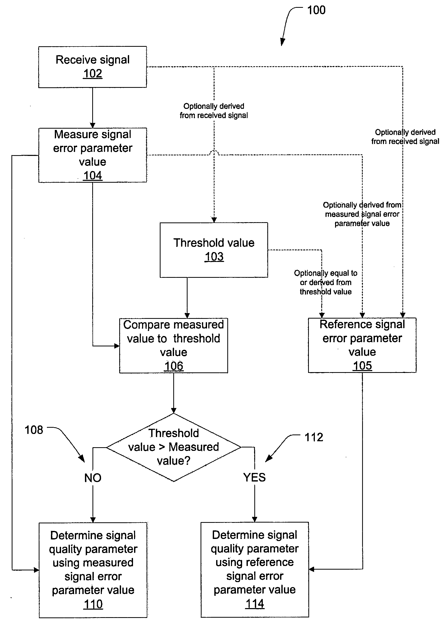
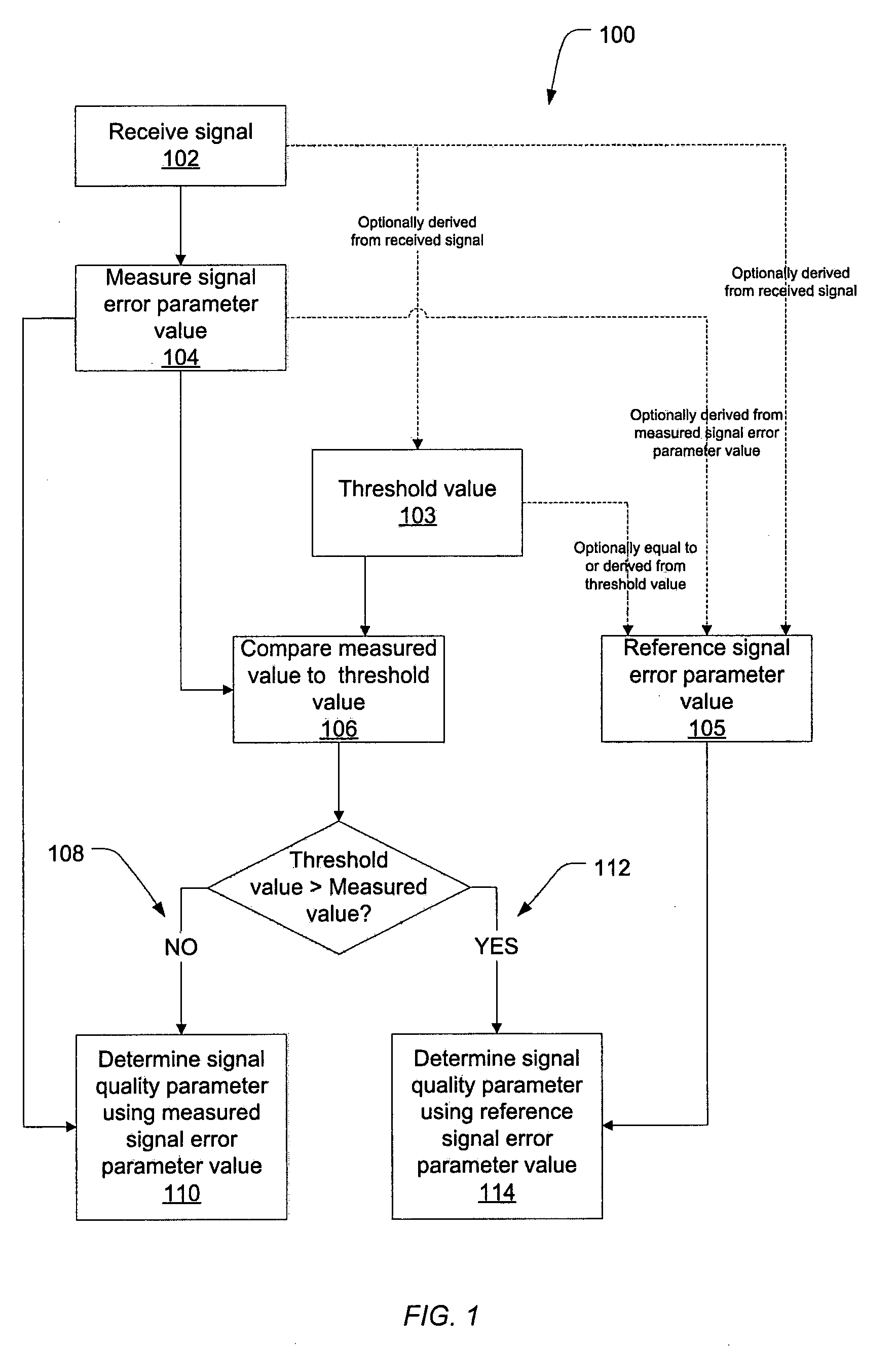
[0025]Turning firstly to FIG. 1. In this example, a method is described for determining a signal quality parameter for a received radio transmission. The method 100 begins with the receiver device, e.g. a user equipment in a cellular telecommunications network, receiving a radio signal in the downlink direction in step 102. Next, in 104, a signal error parameter of the received signal is measured. This measured signal error parameter is compared to a threshold value 103 in step 106.

[0026]The outcome of the comparison of step 106 is used to determine what parameter value is to be used in subsequent steps of the method 100 to calculate the signal quality parameter of interest. In the event (step 108) that the measured signal parameter value is not less than the threshold value 103, the signal quality parameter of interest is calculated using the signal error parameter value measured in step 104. On the other hand, in the event (step 112) that the measured signal parameter value is les...


PUM


Abstract

A method of determining a signal quality parameter in a radio communications device includes: measuring a signal error parameter of a received signal (104); comparing said measured signal error parameter to a threshold level (106), and determining the signal quality parameter on the basis of a reference signal error parameter value (114) in the event that the measured signal error parameter value is less than the threshold level (112).

Description

TECHNICAL FIELD[0001]In broad concept the present invention provides a method of determining a signal quality parameter in a radio communications device.BACKGROUND ART[0002]Although the illustrative embodiments will be described in connection with the measurement of signal quality of a downlink transmission in a wideband code division multiple access (WCDMA) cellular telecommunications network the methods described herein should not be considered limited to this type of transmission or network, but should be considered applicable to other devices and network types.[0003]Overestimating Signal to Interference Ratio (SIR) and Signal to Noise Ratio (SNR) measurements can be a significant problem in some communications systems under certain conditions. Overestimation of these parameters can occur when the measured interference / noise power value underestimates the actual interference or noise power value. Improving the accuracy and reducing the variability of signal error and noise power ...

Claims


Application Information

Patent Timeline
IPC IPC(8): H04B7/216H04W52/00H04W52/12H04W52/24
CPCH04W52/12H04W52/241H04B17/345H04B17/327H04B17/21
Inventor ISAAC, PAULSTANHOPE, DAVIDWANG, XINHUAVASIC, DOBRICA
Owner LENOVO INNOVATIONS LTD HONG KONG
Why Eureka
Try Eureka