Transfer device and image forming apparatus

Inactive Publication Date: 2009-05-21
RICOH KK
View PDF4 Cites 32 Cited by
  • Summary
  • Abstract
  • Description
  • Claims
  • Application Information

AI Technical Summary

Benefits of technology

[0016]It is an object of the present invention to at least

Problems solved by technology

The generated static electricity is accumulated on the members, thus resulting in occurrence of bias in electric potential.
Furthermore, when the sheet material carrying the toner image passes through the vicinity of the members after the toner image is transferred onto the sheet material, an unfixed toner image spoils due to the high potential static electricity accumulated on the members, thus deteriorating image quality such as toner scattering and raggedness of the image.
For example, when the sheet material is formed of a paper an

Method used


Image

  • Transfer device and image forming apparatus
  • Transfer device and image forming apparatus
  • Transfer device and image forming apparatus

Examples


first embodiment

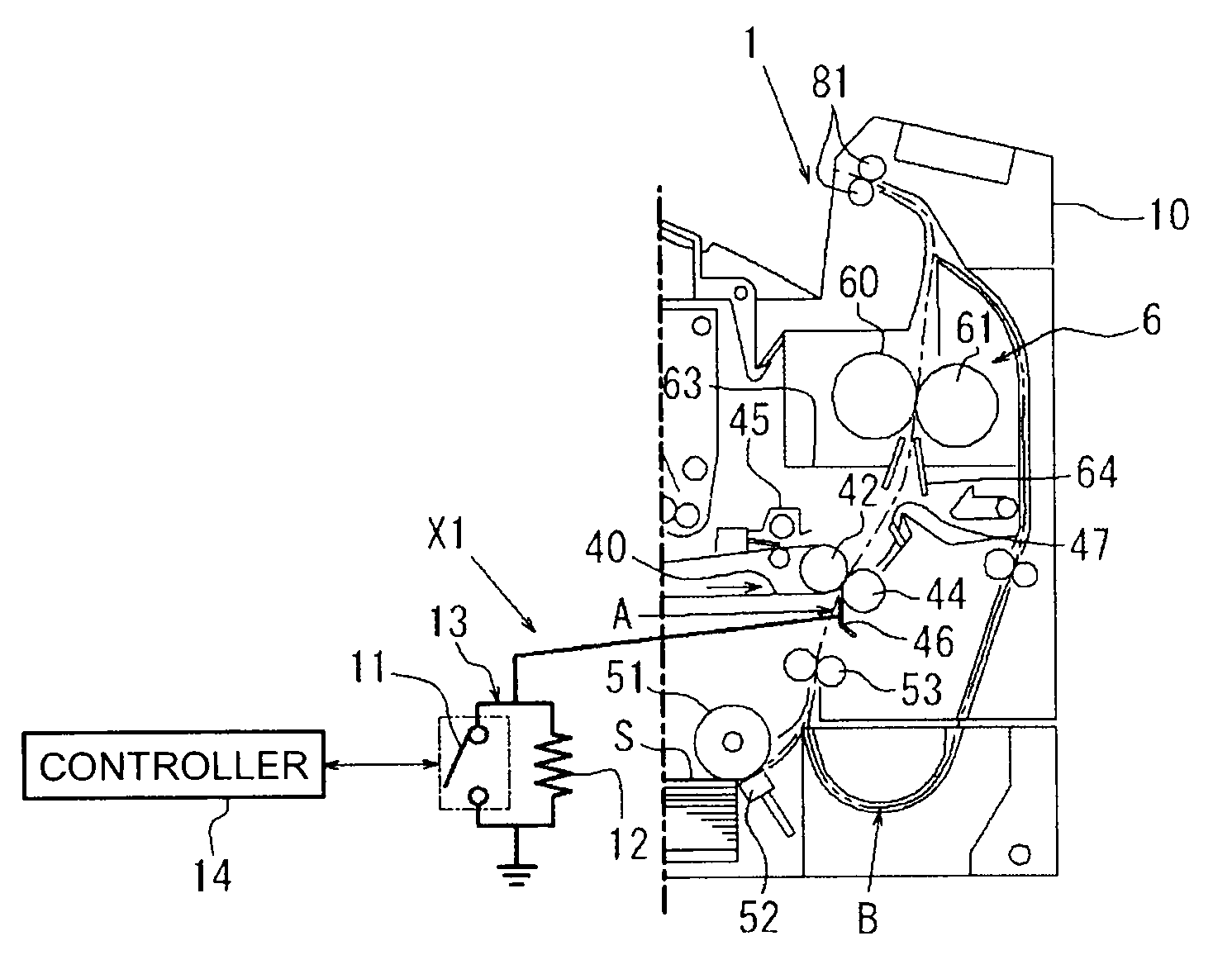
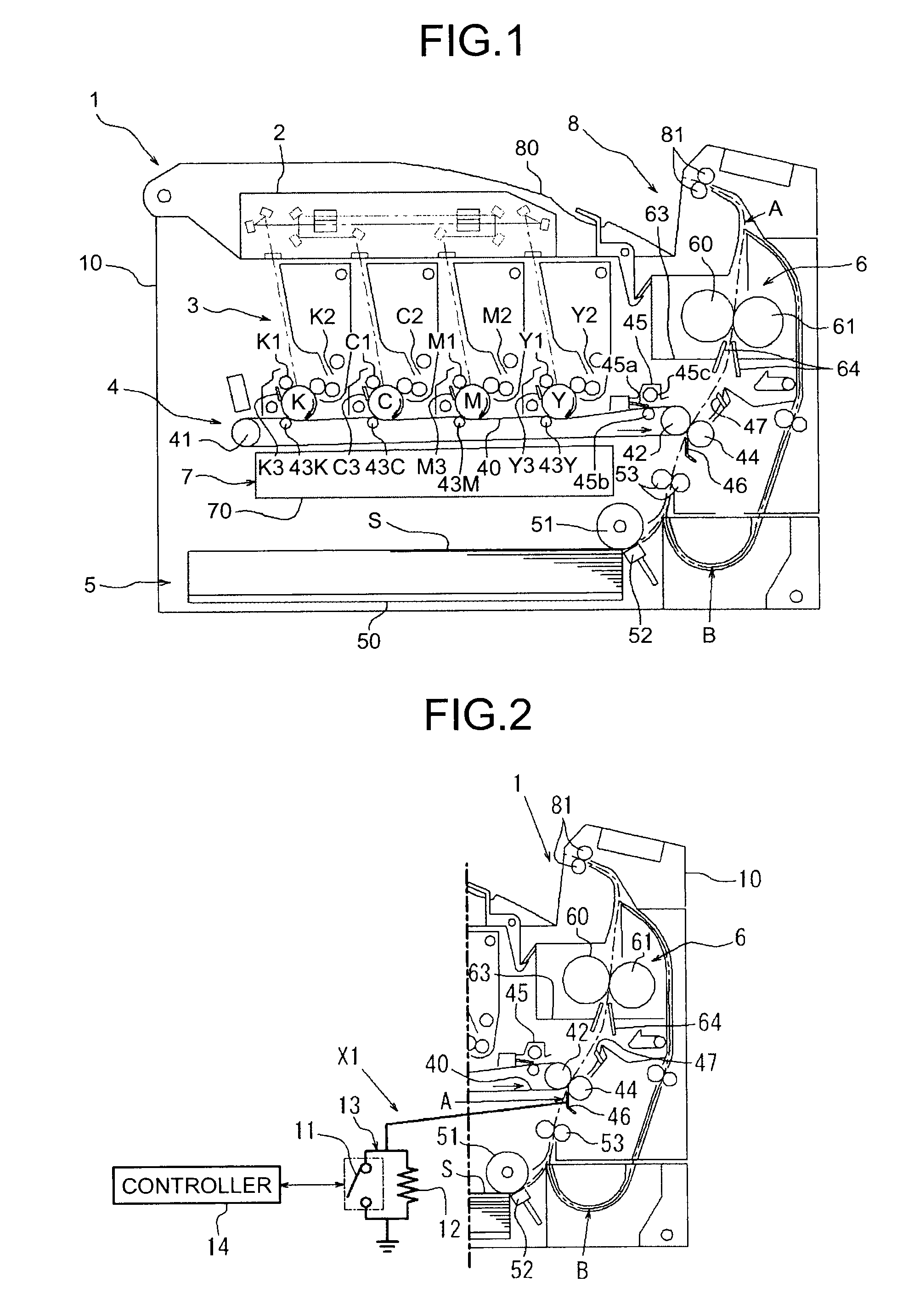
[0050]As shown in FIG. 2, a neutralizing mechanism X1 is arranged in the pre-secondary transfer guide 46 that is the conveying path proximal member. The pre-secondary transfer guide 46 is connected to the ground by a conducting material such as an electric cable via a neutralizing circuit 13 in which a ground switch 11 and a resistor 12 that is a first resistor are electrically and parallely connected.

[0051]The ground switch 11, which includes (not shown) solenoid, is a solenoid switch that carries out on and off operation by the operation of the solenoid. The solenoid is connected to a controller 14 that is a controlling unit of the printer 1 and based on the control signals of the controller 14, the solenoid turns the switch on or off.

[0052]The resistor 12 is set to a predetermined electric resistance that is decided by considering transfer voltage (or transfer current), a volume resistance of the intermediate transfer belt 40, and a volume resistance of the driving roller 42 or ...

second embodiment

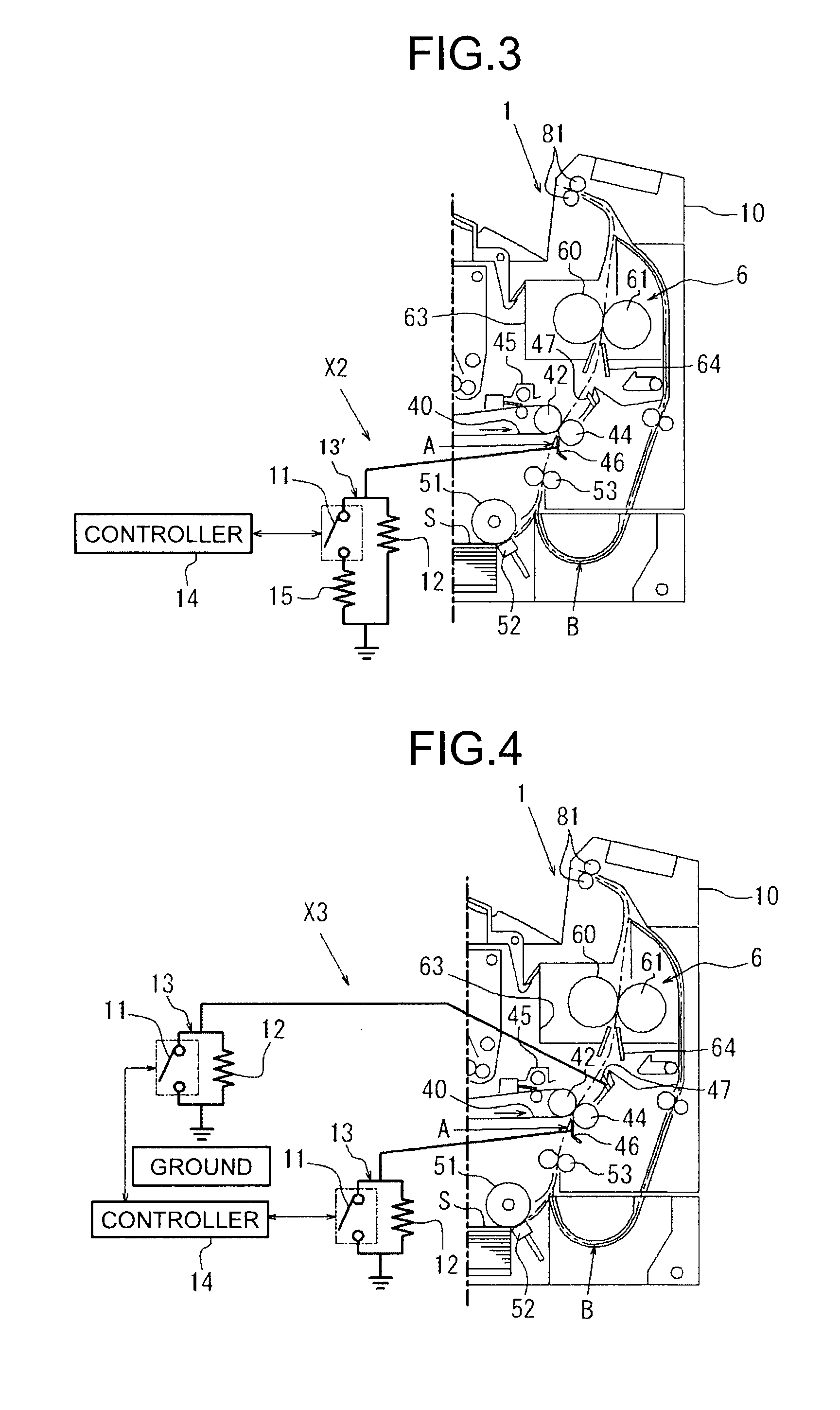
[0067]From a plurality of arranged neutralizing circuits, the neutralizing circuit 13 is explained as an example. The neutralizing circuit 13 can be replaced by the neutralizing circuit 13′ according to the Furthermore, the neutralizing circuit 13 and the neutralizing circuit 13′ can be combined. Whether to use the neutralizing circuit 13 or the neutralizing circuit 13′ can be selected by considering the volume resistance of the conveying path proximal member in which the neutralizing mechanism is arranged. For example, if the pre-secondary transfer guide 46 is formed of the metal product of a small volume resistance, the neutralizing circuit 13′ can be selected. Even if the ground switch 11 is turned on, the neutralization cannot be carried out unless the charge passes through the resistor 15. Thus, as mentioned earlier, the high current does not flow abruptly. Consequently, damaging of the peripheral members such as the electronic components of the neutralizing mechanism can be p...


PUM


Abstract

A neutralizing mechanism is provided on at least one conveying path proximal member installed on a conveying path of a sheet material in a vicinity of a transfer position, and is grounded by using a conducting material. The neutralizing mechanism includes a neutralizing circuit that includes a resistor and a ground switch electrically connected in parallel to each other. The ground switch is turned off at least at a time of applying the transfer bias to prevent a leakage of a transfer current, and turned on for a predetermined time at a time other than the time of applying the transfer bias to earth and remove a static electricity from the conveying path proximal member.

Description

CROSS-REFERENCE TO RELATED APPLICATIONS[0001]The present application claims priority to and incorporates by reference the entire contents of Japanese priority document 2007-301419 filed in Japan on Nov. 21, 2007.BACKGROUND OF THE INVENTION[0002]1. Field of the Invention[0003]The present invention relates to an electrophotographic image forming apparatus such as a copier, a facsimile, a printer, and a multifunction peripheral (MFP) and a transfer device that uses an electrostatic image transfer process, and more particularly, relates to a technology for enhancing a neutralizing mechanism for members arranged in the vicinity of the transfer device used in the image forming apparatus.[0004]2. Description of the Related Art[0005]Generally, in an image forming apparatus, a toner image is formed on an outer peripheral surface of image carrying members such as a photosensitive drum, a photosensitive belt, and an intermediate transfer belt by using an exposure device and a developing device...

Claims


Application Information

Patent Timeline
IPC IPC(8): G03G15/14
CPCG03G15/657G03G15/1675
Inventor SAKASHITA, TAKESHIMEGURO, YUUJIMURAMATSU, TAKERUKICHISE, MITSUTOSHIETOH, TAKUYA
Owner RICOH KK
Why Eureka
Try Eureka