
Feeding apparatus for creation of one or more plugs of compressible material for feeding into a gasifier or reactor

a technology of compressible material and feeding apparatus, which is applied in the direction of conveyors, manufacturing tools, light and heating apparatus, etc., can solve the problems of unpure structure, high equipment requirements, and still had some severe drawbacks, and achieves less prone to congested, large humidity variations, and energy saving

Active Publication Date: 2009-05-21
TK ENERGI +1
View PDF8 Cites 16 Cited by
  • Summary
  • Abstract
  • Description
  • Claims
  • Application Information

AI Technical Summary

Benefits of technology

[0005]In a first aspect according to the present invention is provided an apparatus, which has a primary, and a secondary safety mechanism for preventing the back-draft of for example hot gases from the reactor or gasifier.
[0007]In a third aspect according to the present invention is provided an apparatus, which is capable of handling materials with large variations in humidity.
[0008]In a fourth aspect according to the present invention is provided an apparatus, which is capable of handling materials with large variations in density, particle size and morphology.
[0009]In a fifth aspect according to the present invention is provided an apparatus, which is less prone to congest.
[0010]In a sixth aspect according to the present invention is provided an apparatus, which is energy efficient.
[0011]The novel and unique features according to the present invention whereby this is achieved is that the inner diameter of at least an inlet section extending from the inlet end of said mouthpiece increases towards the exit end, so that an angle between the inner wall of at least the inlet section and the longitudinal axis of the mouthpiece is larger than 0° but less than or equal to 3°. The great advantage of this specific shape is that it allows for the creation of a plug, which is dense enough to withstand a large pressure gradient across the longitudinal direction of the plug. At the same time the risk of blockage of the mouthpiece is significantly lessened, compared to for example hourglass shaped mouthpieces or to mouthpieces with a negative or zero angle between the inner wall and the longitudinal axis of the mouthpiece.

Problems solved by technology

These types of materials are often of uneven structure and un-pure, which puts up high requirements for the equipment used for processing them.
While this feeding apparatus solves several problems of the at the time existing feeding apparatuses, which typically use different types of screw feeders for grinding and feeding, it still had some severe drawbacks.
These drawbacks are evident when the feeding apparatuses of WO 93 / 23709 is used in situations where dense plugs are needed and in situations where the pressure difference across the formed plugs are high, as it will be in relation with many modern reactors.
This result in loosely pressed plugs but still with a high risk of blockage of the mouthpiece as is the case in most other feeders within this field of technology.
Such blockages are unwanted, as they requires full stop of the machinery in order to be taken care of.

Method used


Image

  • Feeding apparatus for creation of one or more plugs of compressible material for feeding into a gasifier or reactor
  • Feeding apparatus for creation of one or more plugs of compressible material for feeding into a gasifier or reactor
  • Feeding apparatus for creation of one or more plugs of compressible material for feeding into a gasifier or reactor

Examples


example

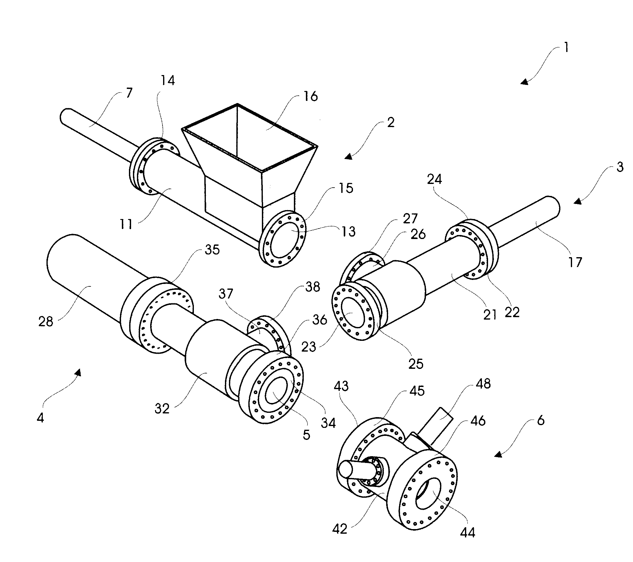
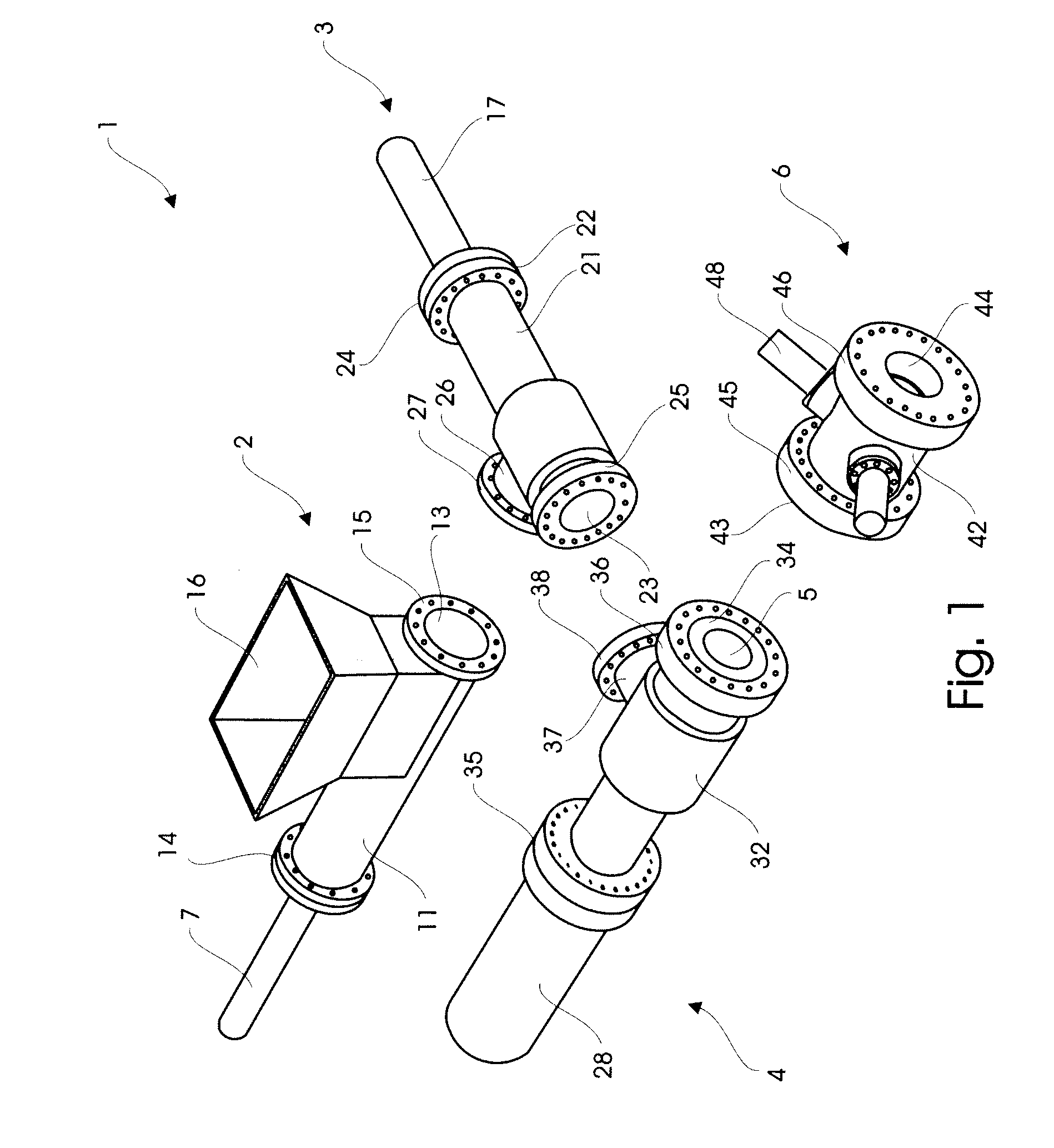
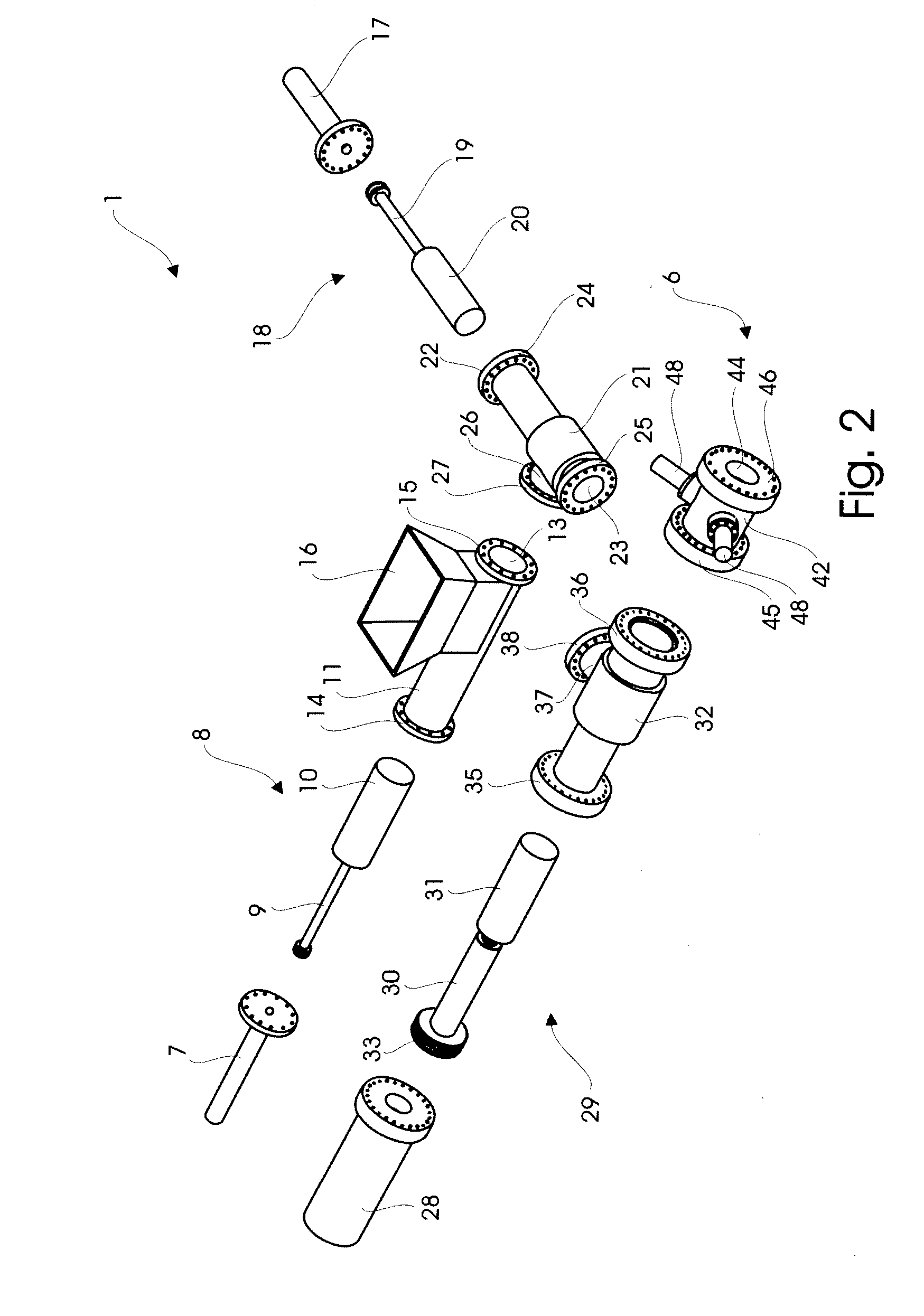
[0075]A compressible material for example wood chip, is fed into the feeding apparatus 1 through the inlet 16, which in the present embodiment is a funnel. The wood chip is by the use of the inner piston part 8 pre-compressed and conveyed to the second piston section 3. From here the wood chip is by the use of the inner piston part 18 of the second piston section 3 further pre-compressed and conveyed to the third and final piston section 4. From the third piston section 4 the now twice pre-compressed material is pressed through the mouthpiece 5 and further into the braking section by the inner piston part 29 of the third piston section 4. The friction shoes 47 regulate the friction between the compressible material / pressed plug and the braking device 6 in order to provide a plug with the most suitable density. The speed of the piston head 31 is measured and the pressure of the friction shoes 47 on the created, pressed plug is regulated on the basis of these speed measurements. For e...


PUM


Abstract

An energy efficient, very flexible and safe feeding apparatus serves for creation of one or more plugs of compressible material for feeding into a gasifier, reactor or other combustion chamber. This apparatus includes a piston feeder with at least three pistons for pre-compressing and delivering compressible material towards a mouthpiece serving as a non-return valve and having an exit end facing a braking device with a friction member for regulating the final degree of compression of the material, and an opposing inlet end for at least partly compressed material. The inner diameter of at least an inlet section extending from the inlet end of the mouthpiece increases towards the first end, so that an angle between the inner wall of at least the inlet section and the longitudinal axis of the mouthpiece is larger than 0° but less than or equal to 3°.

Description

BACKGROUND[0001]The present invention relates to a feeding apparatus for creation of one or more plugs of compressible material for feeding into a gasifier or reactor, wherein the apparatus comprises a piston feeder with at least three pistons for pre-compressing and delivering compressible material towards a mouthpiece serving as a non-return valve and having an exit end facing a braking device with friction means for regulating the final degree of compression of the material, and an opposing inlet end for inlet of at least partly compressed material.[0002]An apparatus of this type is, for example, used in connection with combustion of alternative fuels such as residual products like hay, wood chip, scrap paper and other material, which otherwise will be seen as waste materials. These types of materials are often of uneven structure and un-pure, which puts up high requirements for the equipment used for processing them. An example is hay, which can contain impurities such as sticks...

Claims


Application Information

Patent Timeline
IPC IPC(8): B01J3/02B30B11/00
CPCB30B7/04F23K2203/203F23K3/00B30B11/06
Inventor KOCH, THOMASFRIEHLING, PETER
Owner TK ENERGI
Learn More