
Method for Embedded Integrated End-to-End Testing

a technology of integrated end-to-end testing and testing method, which is applied in the direction of error detection/correction, instruments, transmission, etc., can solve the problems of large integration system testing (ists), large test duration, and high cost and risk, so as to eliminate the risk, expense and time

Inactive Publication Date: 2009-05-21
AT&T INTPROP II L P
View PDF2 Cites 6 Cited by
  • Summary
  • Abstract
  • Description
  • Claims
  • Application Information

AI Technical Summary

Benefits of technology

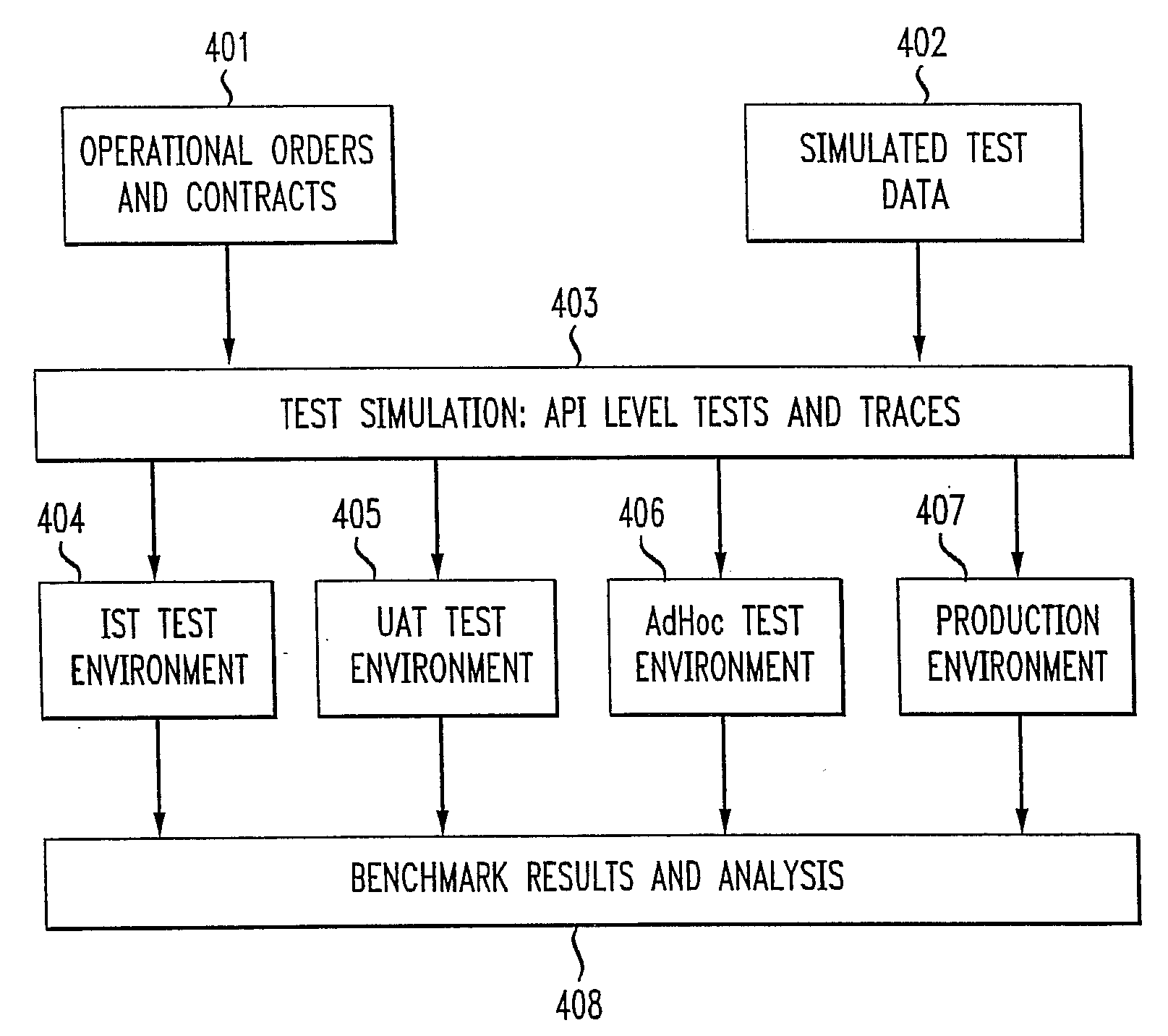
[0003]The present invention essentially solves the aforementioned problems. The present inventors have invented a method and system for automated testing of a system such as a billing module in a telecommunication system. In a first embodiment, test APIs, scenarios and configuration information are embedded into the module itself in a way such that, when testing is desired, tests may be conducted without any need for a dedicated test environment. Tests can be run from within the module itself, thus eliminating the risk, expense and time required to use external testing systems and data to test the module. In another embodiment, operational data such as live operational orders are wrapped in test headers and are used as input data for testing purposes within the billing module. In yet another embodiment, test APIs are embedded into all modules of an operational support system in a way such that complete system end-to-end testing is possible without the use of dedicated external test equipment and processes.

Problems solved by technology

Accordingly, such systems are complex and require careful configuration control.
In the case of today's large converged telecommunication networks, such tests can be correspondingly very large and complex in scope.
As a result of the complexity involved in integrating test equipment and validating test data / scenarios, such large integration systems tests (ISTs) are typically long in duration, expensive and risky.

Method used


Image

  • Method for Embedded Integrated End-to-End Testing
  • Method for Embedded Integrated End-to-End Testing
  • Method for Embedded Integrated End-to-End Testing

Examples


Embodiment Construction

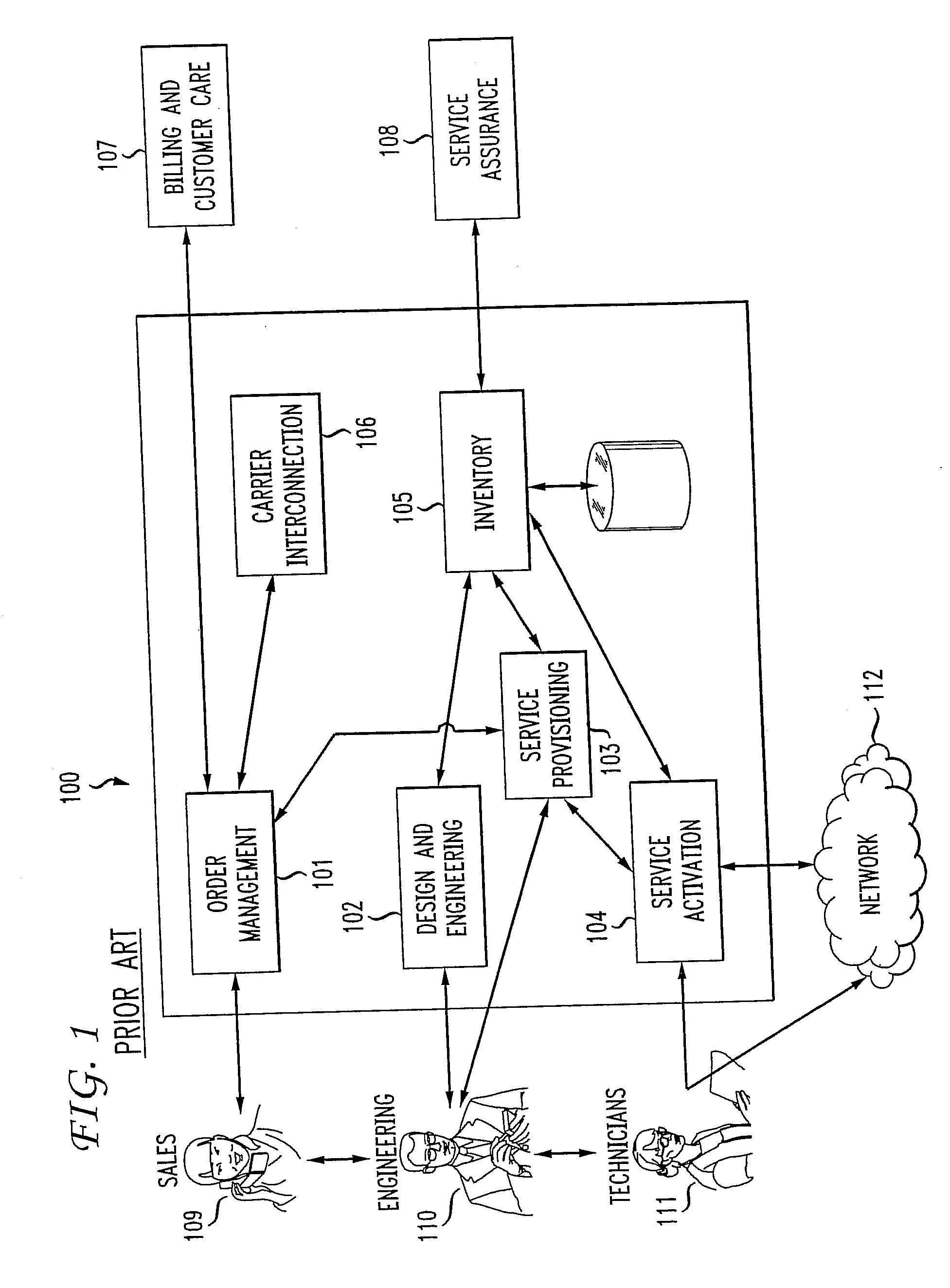
[0010]FIG. 1 shows an illustrative operational support system (OSS) associated with a telecommunication network. OSS 100 has, illustratively, order management module 101, design and engineering module 102, service provisioning module 103, service activation module 104, inventory module 105, carrier interconnection module 106, billing module 107 and service assurance module 108. Illustratively, sales departments / personnel 109 input information (e.g., sales) to the order management module 101 and provide feedback (e.g., requests for improvement to the system) to engineering department 110. Engineering department 110, for example, performs system design and engineering functions using design and engineering module 105; service provisioning using service provisioning module 103 and communicates activation and network configuration requirements to technicians 111. Technicians 111 perform the actual service activation functions and configure 112 according to system requirements such as th...


PUM


Abstract

A method and system for automated testing of a system such as a billing module in a telecommunication system is disclosed. In a first embodiment, test APIs, scenarios and configuration information are embedded into the module itself in a way such that, when testing is desired, tests may be conducted without any need for a dedicated test environment. Tests can be run from within the module itself, thereby eliminating the risk, expense and time required to use external testing systems and data to test the module. In another embodiment, operational data such as live operational orders are wrapped in test headers and are used as input data for testing purposes within the billing module. In this embodiment, test APIs may be embedded into all modules of an operational support system so that complete system end-to-end testing is possible without the use of dedicated external test equipment and processes.

Description

BACKGROUND OF THE INVENTION[0001]As complex converged telecommunication networks designed to provide a wide range of services to customers become more prevalent, the need for thorough testing becomes important prior to operationally releasing any replacement module or improvement to any part of the system. For example, operational support systems (OSSs) in telecommunication systems have many different elements that require frequent updates and improvements when new services are introduced to customers. Such OSS systems typically include order management, design and engineering, carrier interconnection, service provisioning, inventory, service activation, billing, customer care and service assurance modules. These modules are able to interact with each other and various modules and networks and also must be able to accept input from and provide information to external elements, such as sales, engineering and technician personnel. Accordingly, such systems are complex and require care...

Claims


Application Information

Patent Timeline
Patent Type & Authority Applications(United States)
IPC IPC(8): G01R31/28G06F11/00
CPCH04L43/50
Inventor HUSHYAR, KAVEHNADJI, BEHZADTOFIGHBAKHSH, MOSTAFA
Owner AT&T INTPROP II L P
Learn More