Waveguide interface adapter and method of manufacture

a technology of interface adapters and waveguides, applied in the direction of waveguide type devices, basic electric elements, coupling devices, etc., can solve the problems of increased assembly weight, difficulty in mounting and retaining the split ring(s) around the waveguide prior to fastening within the overhousing, and increased overall weight of the assembly

Inactive Publication Date: 2007-11-15
COMMSCOPE TECH LLC
View PDF13 Cites 5 Cited by
  • Summary
  • Abstract
  • Description
  • Claims
  • Application Information

AI Technical Summary

Problems solved by technology

This similarity creates a significant chance of erroneously delivering to the installer two identical split ring halves rather than the required two mating split ring halves, resulting in an unusable assembly.
Also, mounting and retaining the split ring(s) around the waveguide prior to fastening within the overhousing is difficult.
As a result, the overall weight of the assembly is increased along with spacing requirements alongside other equipment.
Another problem with the prior waveguide interfaces is the plurality of unique components and fasteners required.
The plurality of small parts / fasteners creates an opportunity for delivery errors and or for the accidental loss of a part that may also generate a drop hazard.
Any of which results in an unusable interface assembly at the point of installation.
Formed from metal alloys, such as brass, these assemblies have a significant materials cost and weight.
Also, precision machining, co-ordination and inventory of each of these components are significant cost factors.

Method used


Image

  • Waveguide interface adapter and method of manufacture
  • Waveguide interface adapter and method of manufacture
  • Waveguide interface adapter and method of manufacture

Examples


Embodiment Construction

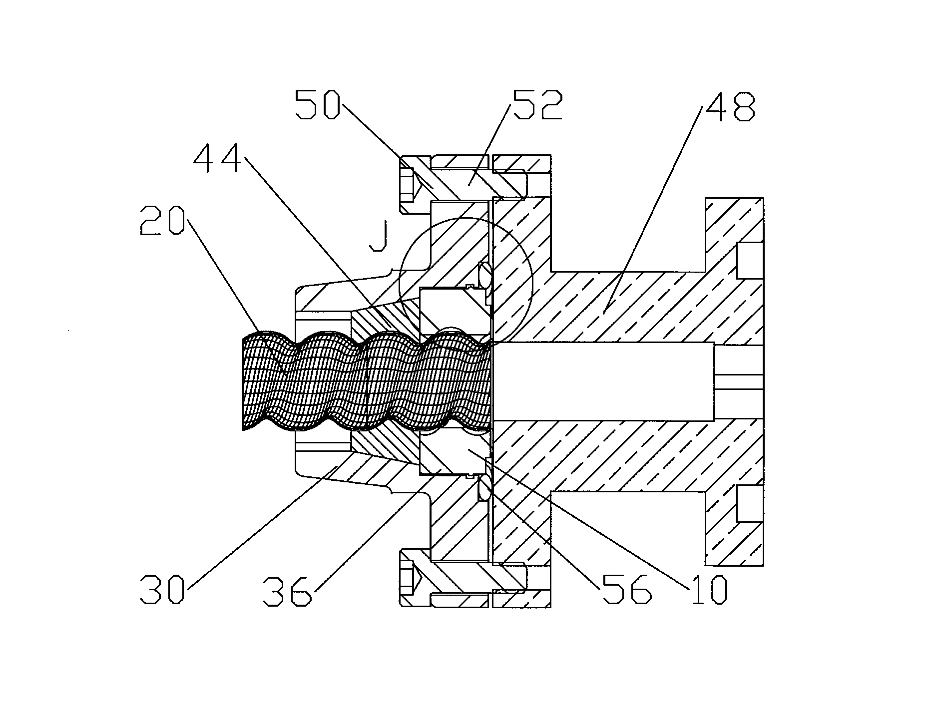
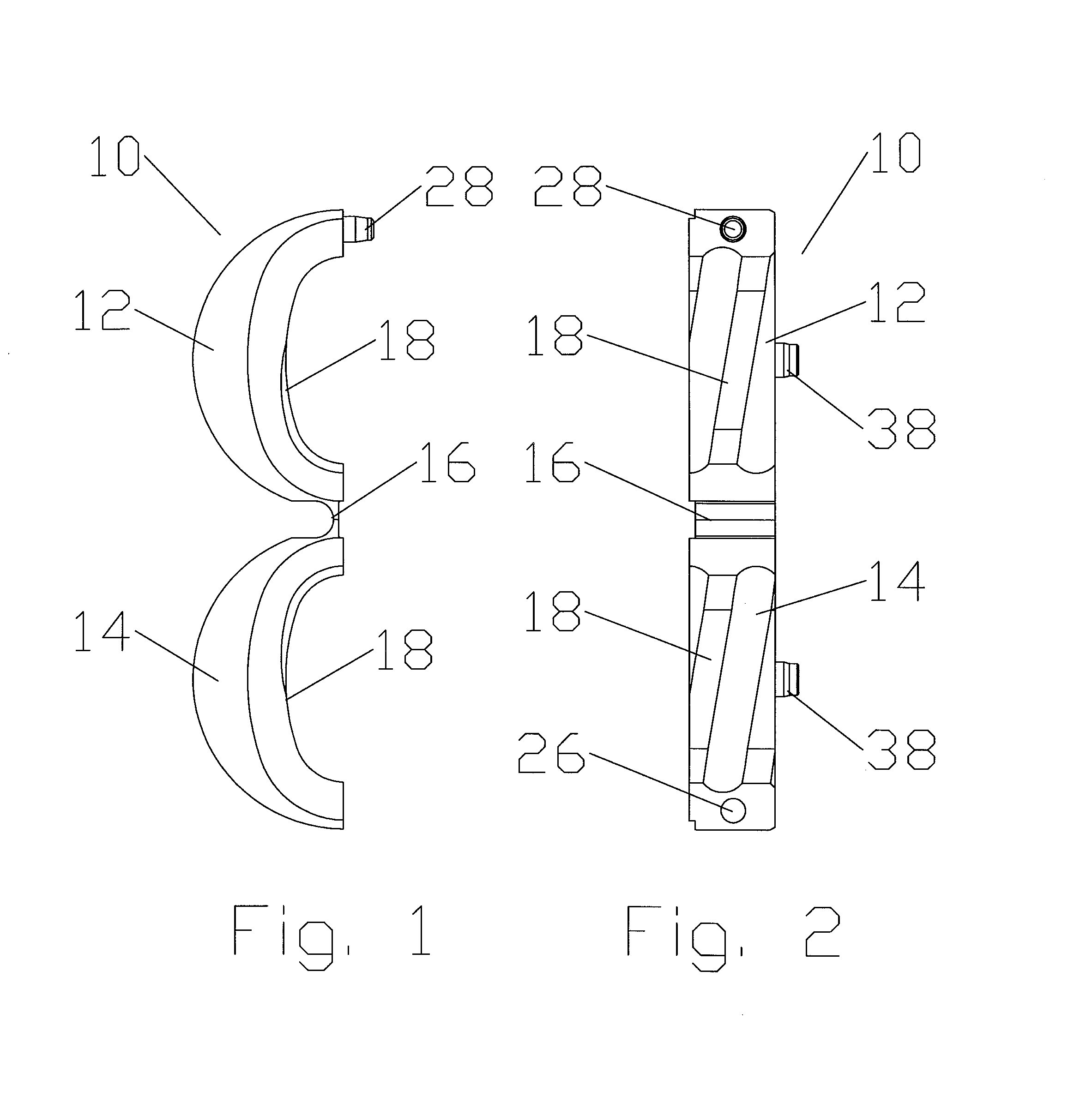
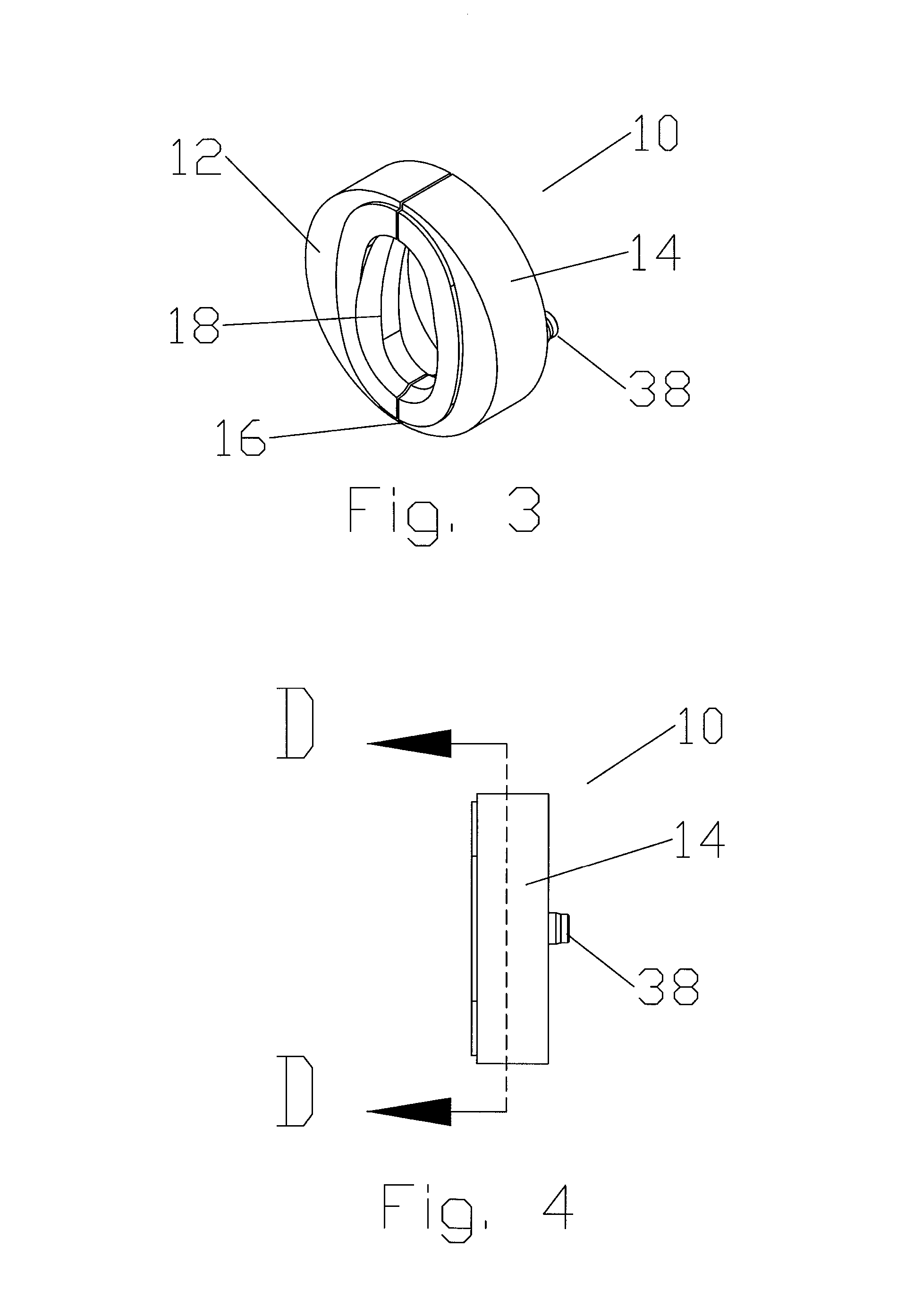
[0031] As shown in FIGS. 1-6, a split ring 10 according to an exemplary embodiment of the invention is formed as a single contiguous component. A first half 12 and a second half 14 of the split ring 10 are joined by a web portion 16. The web portion 16 may be dimensioned with respect to the selected split ring 10 material. For example, where a polymer is applied a thinner web portion 16 may be usable according to elastic properties of the polymer, if any. Where a metal alloy is applied, the web portion 16 preferably has a thickness that allows easy folding of the first and second halves 12, 14 toward one another without requiring application of force multiplication means such as hand tools, and also that is not under or oversized such that the web portion 16 fractures upon folding.

[0032] An inner surface 18 of each of the first and second halves 12, 14 is formed to match corrugations, if any, of the waveguide 20 exterior around which the first and second halves 12, 14 may be folded...


PUM


Abstract

A waveguide interface for a waveguide having a split ring with a first half and a second half joined by a web portion. The split ring first half and second half having an inner surface configured to mate with an exterior of the waveguide, the first half and the second half foldable towards each other and around the exterior of the waveguide, along the web portion. An overbody with a bore is dimensioned to receive the waveguide therethrough; the bore having a shoulder at an interface end dimensioned to receive the split ring.

Description

BACKGROUND [0001] 1. Field of the Invention [0002] This invention relates to waveguides and waveguide interconnection interfaces. More particularly, the invention relates to a waveguide interconnection interface with improved manufacturing cost efficiencies and ease of installation. [0003] 2. Description of Related Art [0004] Waveguides are commonly used for transmitting electromagnetic wave energy from one point to another. [0005] Waveguide interfaces field mountable upon a waveguide end via a mechanical clamping action are known. To retain the waveguide interface upon the waveguide end, a two part split ring with an inner surface that keys with corrugations of the waveguide exterior is fitted around the waveguide. The two part split ring is retained against the waveguide by an overhousing that the two part rings fit into, secured in place via a plurality of screws. The prior waveguide interfaces were sealed by a gasket positioned between the overhousing and the outer surface of th...

Claims


Application Information

Patent Timeline
Patent Type & Authority Applications(United States)
IPC IPC(8): H01P1/04
CPCH01P1/042H01P5/082H01P5/024H01P5/00H01P5/02
Inventor PAYNTER, JEFFREY D.
Owner COMMSCOPE TECH LLC
Why Eureka
Try Eureka