Gearbox for cold metal cutting machine

a cold metal cutting machine and gearbox technology, applied in the direction of metal sawing devices, manufacturing tools, rigid support of bearing units, etc., can solve the problems of shafts and other components, difficult to remove later for service, and virtually impossible to adjust or disassemble press-fitted parts, etc., to achieve easy field replacement and easy removal

Inactive Publication Date: 2008-01-01
SALVARYAN ASHOT
View PDF17 Cites 5 Cited by
  • Summary
  • Abstract
  • Description
  • Claims
  • Application Information

AI Technical Summary

Benefits of technology

[0037]It is a primary object of the present invention to advance the state of the art in the field of cold metal cutting machines with regard to overall produceability and serviceability, particularly directed to the speed reduction gearbox module which provides the power train from the motor to the saw blade.
[0038]It is an object to improve the serviceability of the gearbox module so that worn component parts can be readily replaced in a field service environment with ordinary hand tools thus eliminating the expense and delay of present practice of having to ship the heavy machines to a factory service facility due to inherent difficulties of disassembly and reassembly that require special tools such as gear pullers, and often require special and potentially harmful heating of the entire module and / or hammering on the shafts and stressing the thrust bearings in attempts to dislodge press-fitted components that have become tightly seized in place.
[0043]It is an overall object to replace the five troublesome press-fit attachments, of the seven indicated above, found in a conventional cold metal cutting machine gearbox, with slide-fit alternatives that enable service repair and maintenance to be performed readily in a field environment with only regular tools and no need for hammering, heating, forceful disassembly or special pulling tools.SUMMARY OF THE INVENTION
[0044]The abovementioned objects have been accomplished by the present invention which introduces the following six aspects of improvement for cold metal cutting machines with regard to improved serviceability and replacement of practically all components in a field environment without hammering, heating, excessive disassembly or requiring a special puller tool:
[0047](3) providing, for mounting the main high speed thrust bearing, a sleeved faceplate adaptor in place of the present flat ring cover, such that the outer ring of the main thrust bearing is press-fitted to the inside wall of the adaptor sleeve, which in turn is a slide-fitted at its outside wall into a machined enlarged opening in the gearbox bulkhead, thus accomplishing easy slide-fit removal of the main thrust bearing for service purposes;
[0050](6) configuring the low speed shaft with a separate and easily removable saw rotor that enables easy field replacement of the low speed shaft oil seal without requiring total disassembly and shaft removal.

Problems solved by technology

Assembly, adjustment or disassembly of press-fitted parts are virtually impossible as a field service operation since press-fitted parts cannot normally be shifted or disassembled by hand or by hand tools, and may require specialized heating.
These components become tightly seized together in place, such that their later removal for service is extremely difficult, requiring hammering and / or heating that is potentially damaging to bearings, shafts and other components.
Replacement of these thrust bearings is so extremely difficult, problematic and costly, and almost impossible to perform in a satisfactory manner under field conditions because of the harmful hammering and / or heating, and special pulling tools required to remove the original force-fitted thrust bearings, with high risk of damage and distortion.
Overall in practice, replacement of thrust bearings, high speed shaft, worm wheel pinion and / or oil seals are regarded as so difficult that such replacement is not considered viable in the field, consequently the entire heavy saw and gearbox assembly must be shipped to the factory for repair, often at a great distance and at great expense and down time.

Method used


Image

  • Gearbox for cold metal cutting machine
  • Gearbox for cold metal cutting machine
  • Gearbox for cold metal cutting machine

Examples


Embodiment Construction

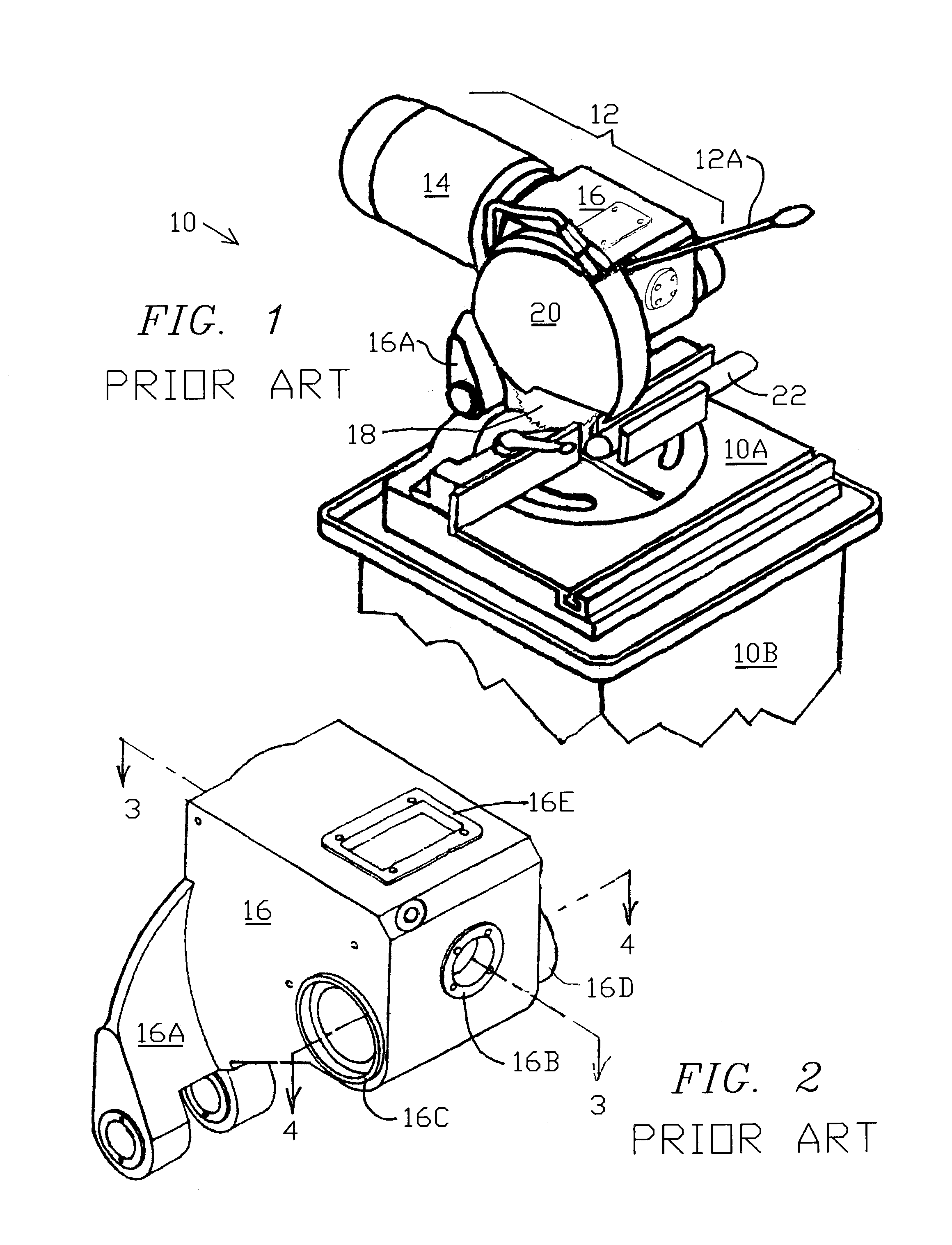
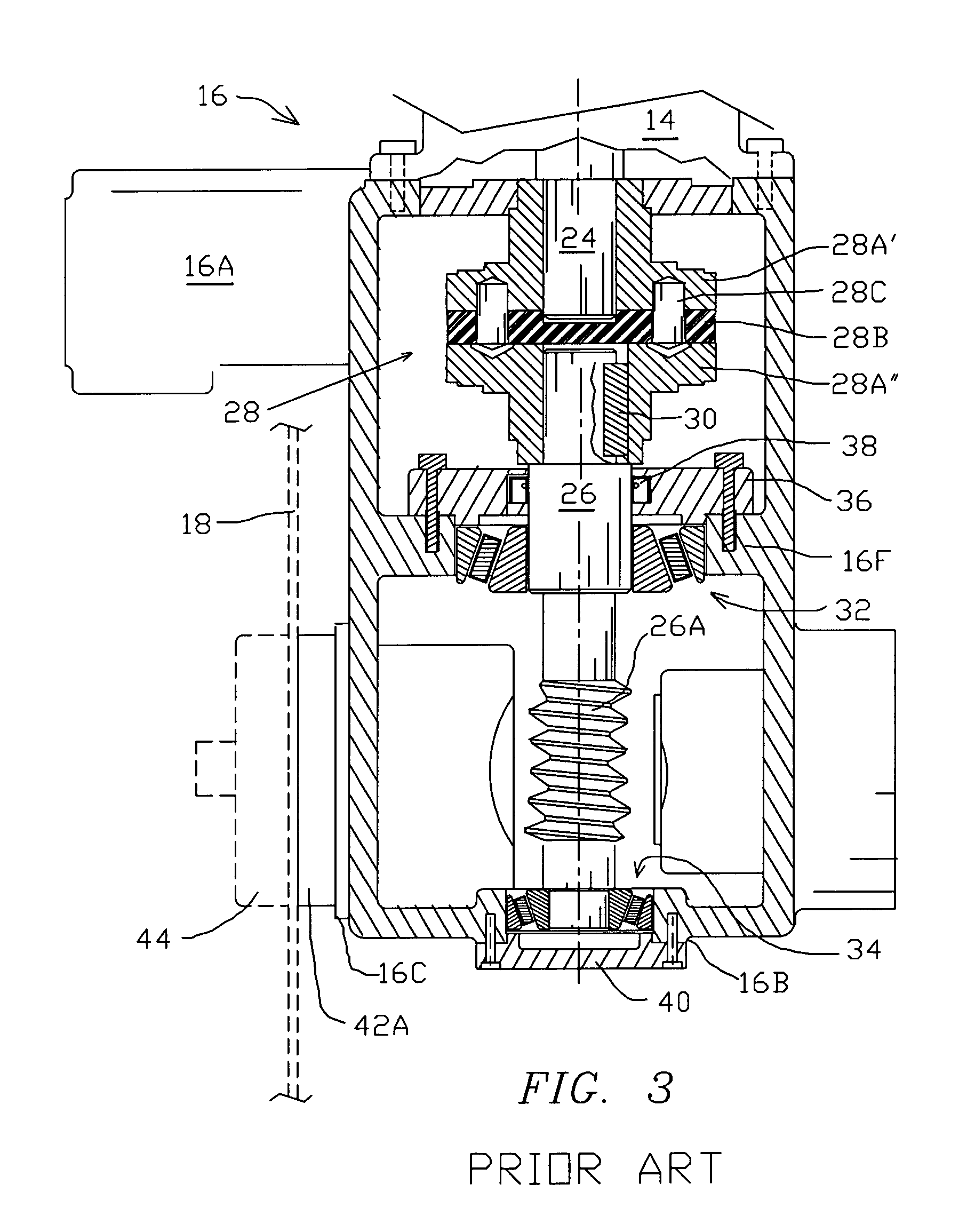
[0058]FIGS. 1, 2, 3 and 4 have been described above in connection with the discussion of known art.

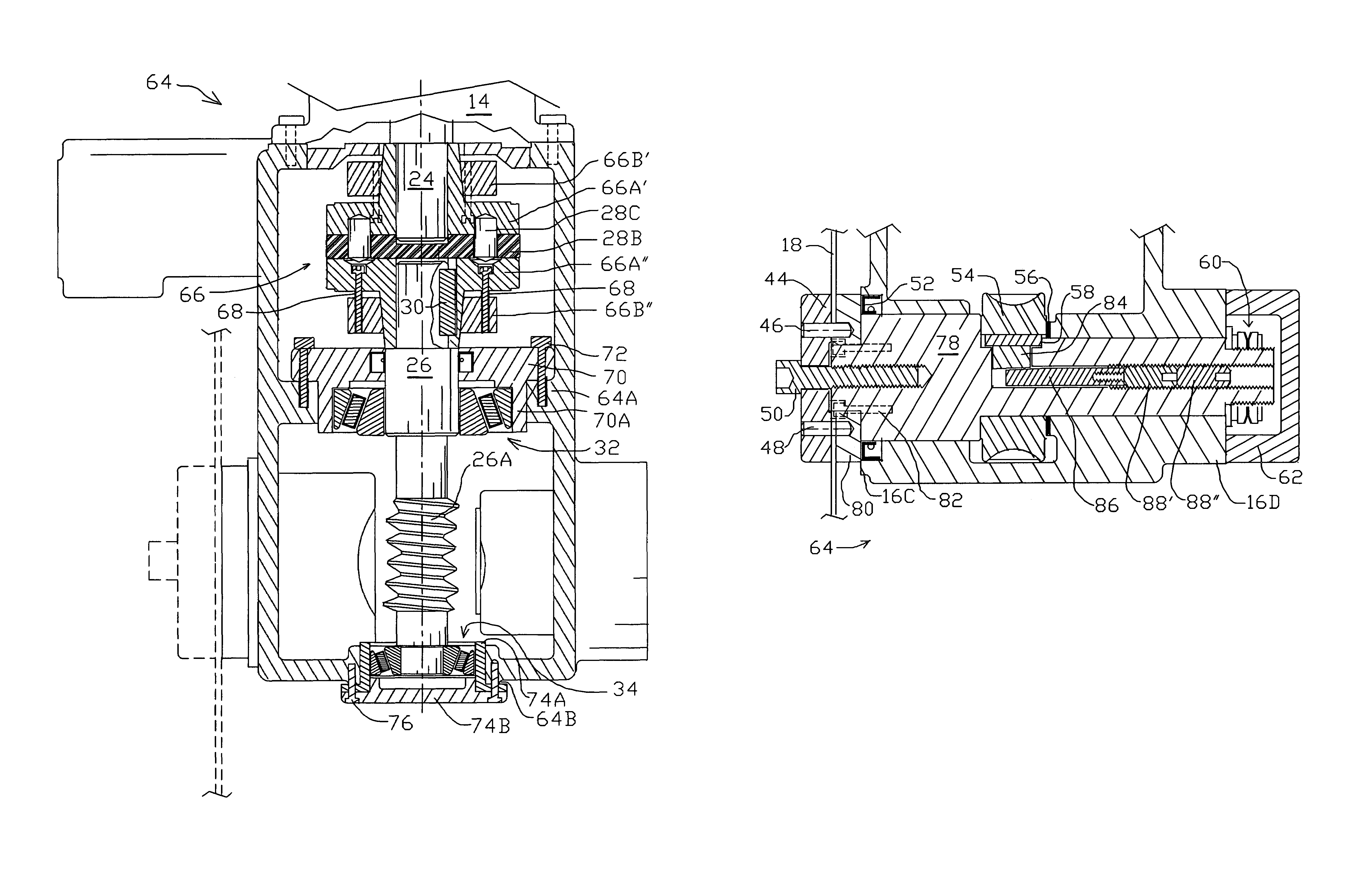
[0059]FIG. 5 shows in cross-section the high speed motor-driven shaft system of a gearbox 64 incorporating improvements in accordance with the present invention. As in FIG. 3, the cross-section in FIG. 5 is taken on a horizontal plane centered on the high speed shaft 26 in the upper portion of the gearbox. In motor coupling 66, the driving and driven members 66A′ and 66A″ are identical, each configured with an extending tapered sleeve, typically at a 2 degree angle, interfacing the similarly tapered bore of a surrounding compression collar 66B′ / 66B″ of hard steel engaged by four machine screws 68 traversing member 66A′ / 66A″ each located co-linearly relative to a corresponding one of the four drive pins 28C.

[0060]As in the conventional couplings depicted in FIG. 3, the gearbox of the present invention utilizes 3 conventional keys and associated keyways: one in low speed shaft 78 (FIG. 6...


PUM

PropertyMeasurementUnit
diameteraaaaaaaaaa
angleaaaaaaaaaa
diameteraaaaaaaaaa

Abstract

Improved serviceability of cold metal cutting machines is accomplished in a modified gearbox structure enabling several annular components that are conventionally attached by press-fit to be attached instead by slide-fit for easy removal and replacement, eliminating hammering and / or heating required conventionally to release press-fit components. Press-fitting of a motor shaft coupling is eliminated by introduction of clamping slide-fit structure. Press-fits of two thrust bearings to the housing are eliminated by introduction of slide-fit adaptors. Instead of the conventional practice of making the saw rotor integral with the low speed shaft, a separate saw rotor bolted to the shaft enables easy replacement of the oil seal.

Description

FIELD OF THE INVENTION[0001]The present invention relates to the field of metal cutting machines, and more particularly it relates to the structure of a gearbox and associated key components thereof for an overhead circular cold metal cutting machine, providing improvements that greatly facilitate initial manufacture, assembly, disassembly, repair and service thereof.BACKGROUND OF THE INVENTION[0002]In the field of metal cutting a particular type of cold metal cutting machine has evolved to a somewhat standard configuration: typically an overhead type with a circular saw blade, e.g. 14 inch diameter, running at low speed, typically within a range of 20 to 120 r.p.m. and typically equipped with a recycling liquid coolant system to prevent overheating of the blade. The cutting operation can be considered a metal milling operation.[0003]To meet stringent requirements for cutting hard metal such as stainless steel, cold metal cutting machines must be designed and built for much heavier ...

Claims


Application Information

Patent Timeline
Patent Type & Authority Patents(United States)
IPC IPC(8): F16C35/00
CPCB23D47/12
Inventor SALVARYAN, ASHOT
Owner SALVARYAN ASHOT
Why Eureka
Try Eureka