
Scan-load-based dynamic scan configuration

a dynamic scan and scan load technology, applied in the field of scan configuration, can solve the problems of limiting the optimal efficiency and effectiveness of these applications, adding additional design development time, and costing considerable interconnect routing spa

Active Publication Date: 2009-05-21
CHEN XINGHAO
View PDF6 Cites 10 Cited by
  • Summary
  • Abstract
  • Description
  • Claims
  • Application Information

AI Technical Summary

Benefits of technology

[0016]Thus, an object of the embodiments of the present invention is to provide a scan-load-based (SLB) dynamic scan configuration, which avoids the disadvantageous of the prior art.

Problems solved by technology

With these techniques, scan configurations—once the circuit structures are placed on silicon—cannot be changed in post-silicon processes, such as test, diagnosis, and debug, limiting the space for optimal efficiency and effectiveness of these applications.
These methods use large amount of interconnect resources to distribute many configuration or decoded address signals.
As large designs often contain more than 250 k scan cells, this DFT effort adds additional design development time and sometimes interferes with timing and other design issues, such as interconnect routing contention.
The above mentioned various MUX-based dynamic scan methods are not good candidates for this scan-load-based dynamic scan configuration that reconfigures scan structures via scan-load operation, to thereby eliminate interconnect network distributing configuration signals because more or less these methods use interconnect, and hence additional routing space, to distribute configuration signals.
This direct-control via PIs provides the most flexibility to reconfigure and / or manipulate scan data, with the cost of using considerable interconnect routing space.

Method used


Image

  • Scan-load-based dynamic scan configuration
  • Scan-load-based dynamic scan configuration
  • Scan-load-based dynamic scan configuration

Examples


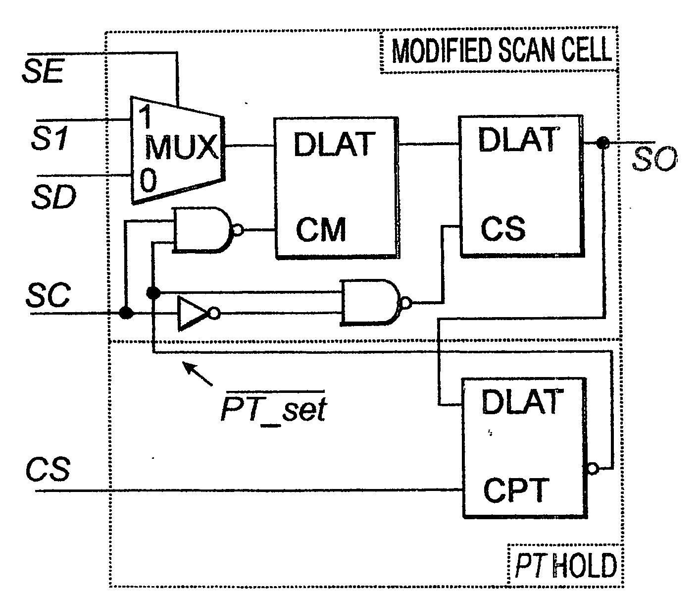
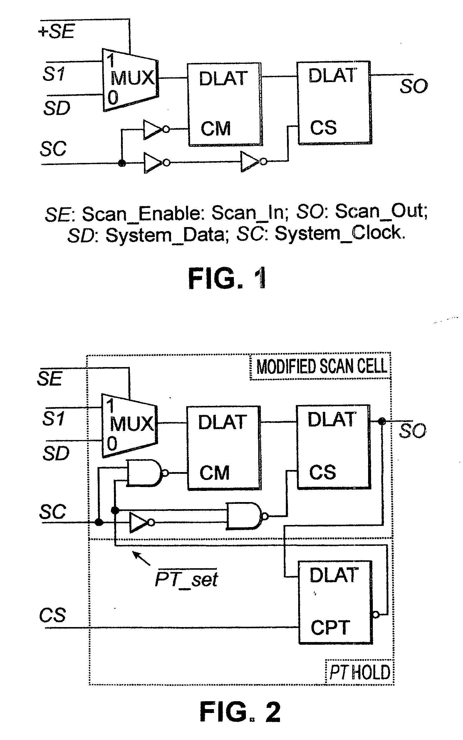
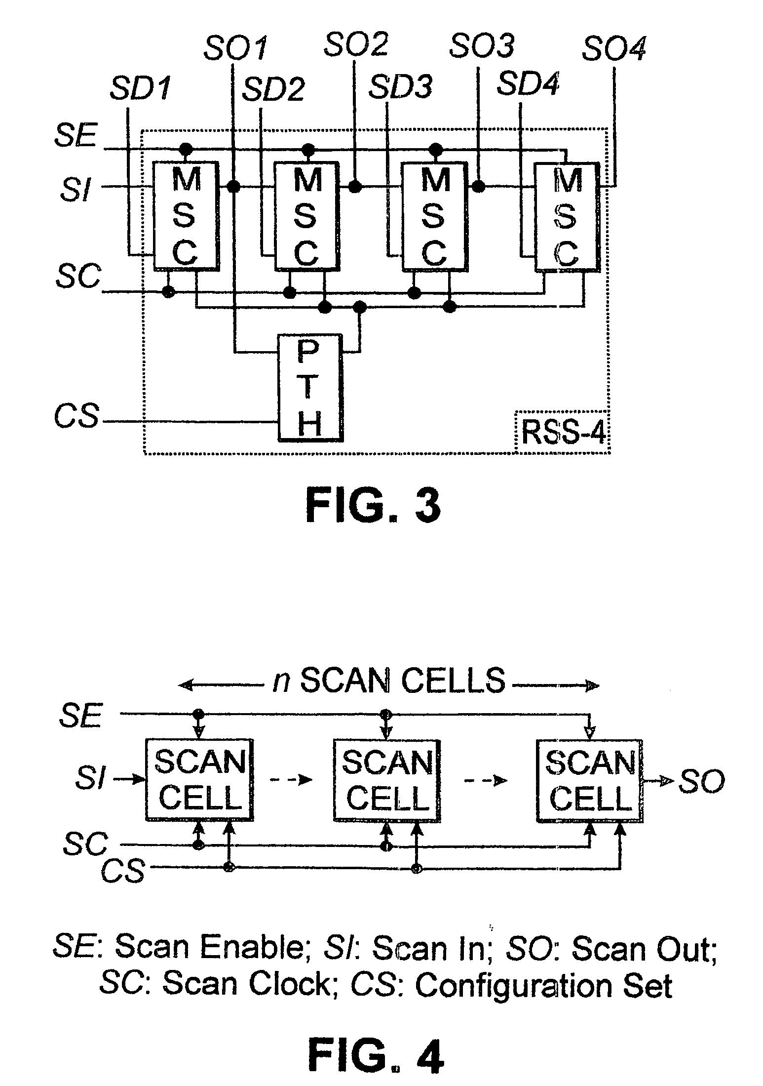
Embodiment Construction

A. The Configuration

[0033]Proven scan methodologies, as already mentioned, remain to be the main DFT vehicles in ASIC design implementations for years to come, and a scan-load-based dynamic scan configuration that reconfigures scan structures via scan-load operation, to thereby eliminate interconnect network distributing configuration signals that are to be defined at the implementation platform level.

[0034]The embodiments of the present invention employ scan-load operation to distribute configuration data to scan cells before a configuration-set signal, which is distributed to each reconfigurable scan cell or segment (a small section of scan cells in adjacent / consecutive shift positions) is applied to set the new configuration into effect. After the scan-load, the configuration data captured in each scan cell indicates whether or not the scan cell is to be set to a pass-through (PT) mode in the new configuration. After the configuration-set signal is applied, scan structures can be...


PUM


Abstract

A scan-load-based (SLB) dynamic scan configuration reconfigures scan structures via scan-load operation, thereby eliminating interconnect network distributing configuration signals, and employs common scan circuitry identical for designs at mask level and is suitable for ASIC implementations. The architecture includes reconfigurable scan cells, apparatus for distributing configuration data to the reconfigurable scan cells and for determining desired reconfiguration data for each of the reconfigurable scan cells, and a configuration-set (CS) signal. Each of the reconfigurable scan cells has a pass-through (PT) mode in which data input, either a scan-in (SI) or a system-data (SD) of the scan cell, is transparently passed to a scan-out (SO) terminal of the scan cell without requiring a pulse on a shift clock (SC). The configuration-set (CS) signal communicates with each of the reconfigurable scan cells. A pulse on the configuration-set (CS) signal triggers PT Hold latches to capture configuration data from corresponding slave latches, which in turn set configurations of each of the reconfigurable scan cells.

Description

THE CROSS REFERENCE TO RELATED APPLICATIONS[0001]The instant nonprovisional patent application is a national stage application of, and claims priority from, International Application Number PCT / US2007 / 016088, filed on Jul. 16, 2007, by Xinghao Chen, which in turn claims priority from provisional patent application No. 60 / 831,261, filed on Jul. 14, 2006, by Xinghao Chen, and which are both incorporated herein by reference thereto.THE BACKGROUND OF THE INVENTION[0002]A. The Field of the Invention[0003]The embodiments of the present invention relate to a scan configuration, and more particularly, the embodiments of the present invention relate to a scan-load-based dynamic scan configuration.[0004]B. The Description of the Prior Art[0005]Various scan design methodologies1 have been successfully used in digital systems and credited with improved testability, reduced cost of test and diagnosis, reduced time for process and system debugging, better system maintenance and serviceability, et...

Claims


Application Information

Patent Timeline
Patent Type & Authority Applications(United States)
IPC IPC(8): G01R31/3177G06F11/25
CPCG01R31/318536
Inventor CHEN, XINGHAO
Owner CHEN XINGHAO
Learn More