Valve timing control apparatus

a timing control and valve technology, applied in the direction of non-mechanical valves, couplings, machines/engines, etc., can solve the problems of degrading the response in advance operation, insufficient working fluid in the advance chamber,

Inactive Publication Date: 2009-05-28
DENSO CORP
View PDF2 Cites 62 Cited by
  • Summary
  • Abstract
  • Description
  • Claims
  • Application Information

AI Technical Summary

Benefits of technology

[0010]To achieve the objective of the present invention, there is provided a valve timing control apparatus for controlling valve timing of a valve that is opened and closed by a camshaft through torque transmitted from a crankshaft in an internal combustion engine, the valve timing control apparatus including a first rotor, a second rotor, and a controller. The first rotor is rotatable with the crankshaft. The second rotor is rotatable with the camshaft. The second rotor and the first rotor define therebetween an advance chamber and a retard chamber, which are circumferentially arranged one after another. The second rotor drives the camshaft with respect to the crankshaft in an advance direction when working fluid is supplied to the advance chamber. The second rotor drives the camshaft with respect to the crankshaft in a retard direction when working fluid is supplied to the retard chamber. The controller includes a supply passage, first and second drain passages, a spool valve, at least one connection passage, and at least one check valve. Working fluid is supplied through the supply passage from an external fluid supply source. Working fluid is discharged through the first and second drain passages, wherein the controller controls a connection state of each of the supply passage and the first and second drain passages with a corresponding one of the advance chamber and the retard chamber. The spool valve includes a spool, which is reciprocably movable. The spool valve connects the supply passage to the advance chamber and connects the first drain passage to the retard chamber by moving the spool to an advance position in order to advance a phase of the camshaft with respect to the crankshaft. The spool valve connects the supply passage to the retard chamber and connects the second drain passage to the advance chamber by moving the spool to a retard position in order to retard the phase. The at least one connection passage connects the supply passage to a corresponding one of the first and second drain passages when the spool is moved to one of the advance position and the retard position. The at least one check valve is provided respectively in the at least one connection passage. The at least one check valve allows working fluid to flow in a first direction from the corresponding one of the first and second drain passages toward the supply passage. The at least one check valve limits working fluid from flowing in a second direction from the supply passage toward the corresponding one of the first and second drain passages.

Problems solved by technology

As a result, when the amount of fluid supply from the pump is relatively small, the working fluid may become insufficient in the advance chamber disadvantageously.
Accordingly, when the application direction of the variable torque is reversed, the shortage of the working fluid in the chamber may cause and the retard of the camshaft, and as a result, the response in the advance operation may be degraded disadvantageously.

Method used


Image

  • Valve timing control apparatus
  • Valve timing control apparatus
  • Valve timing control apparatus

Examples


first embodiment

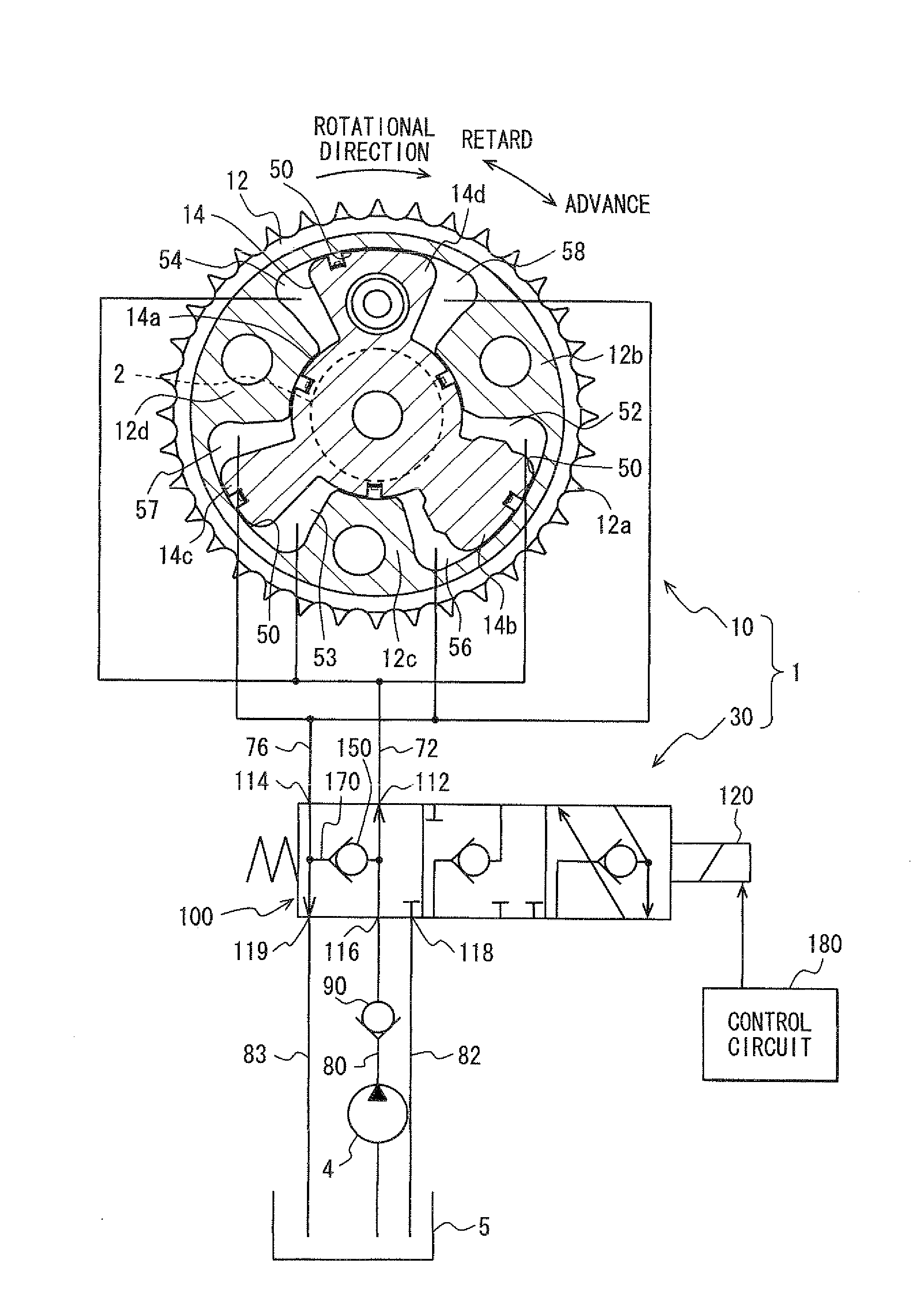
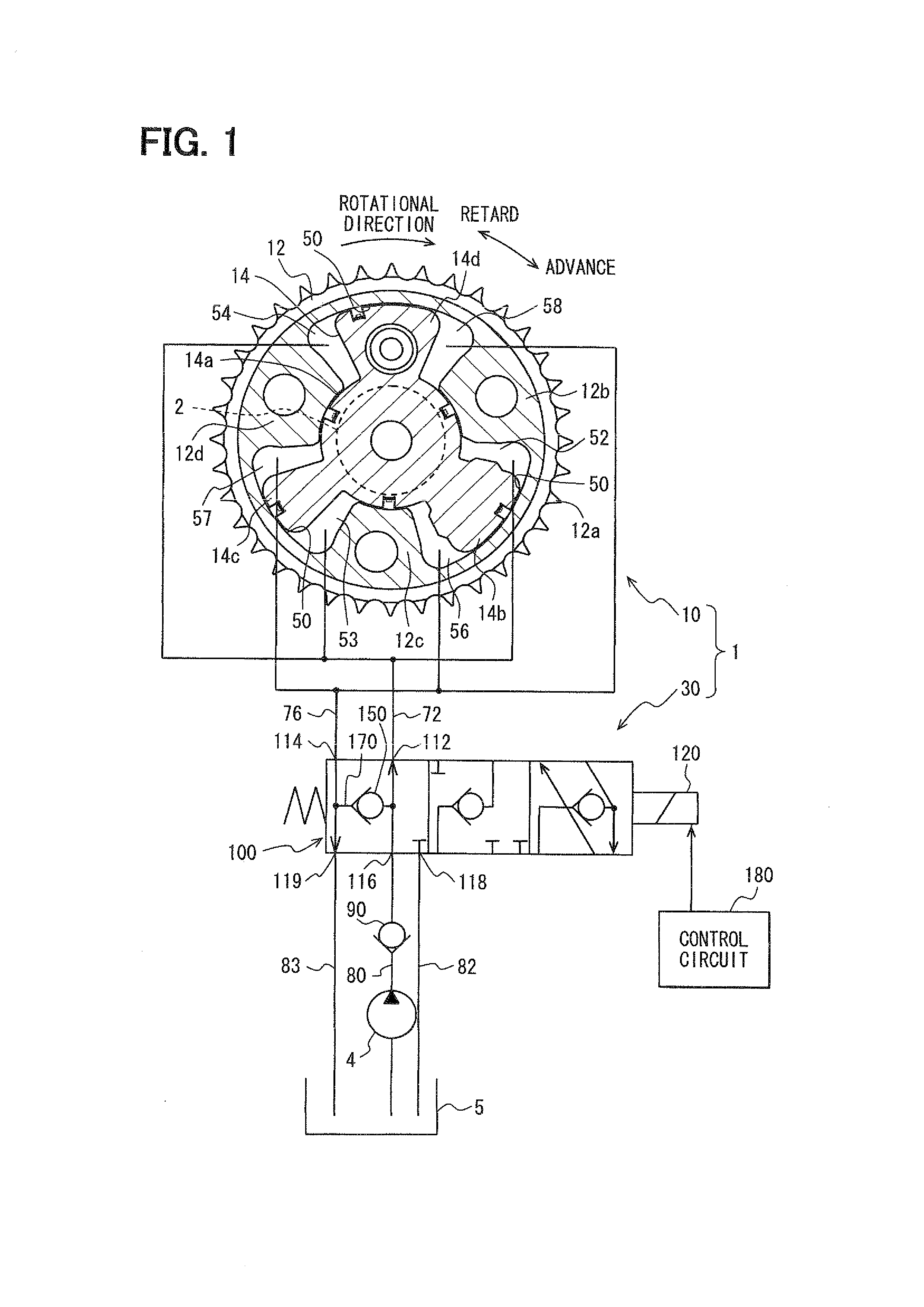
[0047]FIG. 1 shows an example in which a valve timing control apparatus 1 according to a first embodiment of the present invention is applied to a vehicle internal combustion engine. The valve timing control apparatus 1 which is a hydraulic apparatus using hydraulic oil serving as “working fluid” controls valve timing of an intake valve serving as a “valve”.

(Basic Components)

[0048]Hereinbelow, basic components of the valve timing control apparatus 1 will be described. The valve timing control apparatus 1 has a driving unit 10 and a controller 30. The driving unit 10 is provided in a driving force transmission system to transmit a driving force of a crankshaft (not shown) of the internal combustion engine to a camshaft 2 of the internal combustion engine, and is driven with hydraulic oil. The controller 30 controls supply of hydraulic oil to the driving unit 10.

(Driving Unit)

[0049]In the driving unit 10, a housing 12 has a cylindrical sprocket 12a, and multiple shoes (or lobes) 12b t...

second embodiment

[0092]The second embodiment of the present invention is a modification of the first embodiment. As shown in FIGS. 8, 9, in a spool valve 202 in a controller 200 according to the second embodiment, a first check valve 210 is provided in a first connection passage 220, and a second check valve 230 is provided in the second connection passage 240.

[0093]More particularly, as shown in FIGS. 9 to 11 the first connection passage 220 is formed in the spool 130 of the spool valve 202, and the first connection passage 220 has one ends 220a that are opened at multiple positions in the outer peripheral surface of the spool 130, which are located between the advance selection land 134 and the retard selection land 136. In the above, the advance selection land 134 and the retard selection land 136 are located on both axial sides of a gap that always communicates with the supply port 116. Further, the other ends 220b of the first connection passage 220 are opened in other multiple positions in the...

third embodiment

[0113]The third embodiment of the present invention is a modification of the second embodiment. As shown in FIGS. 14, 15, in a controller 300 according to the third embodiment, drain passages 302, 303, which communicates with the drain ports 118, 119, communicate with each other, and hydraulic oil is discharged through a common passage 306 to the oil pan 5. In the above configuration, the common passage 306 is provided on a side of the drain passages 302, 303 opposite to a spool valve 304.

[0114]Further, as shown in FIG. 15, the check valves 210, 230 included in the spool 130 are provided with pressing members 316, 336. The pressing member 316 of the first check valve 210 is provided in the first connection passage 220 between (a) the retainer 215 and (b) an annular wall surface 318 that radially inwardly projects from the inner peripheral surface of the first connection passage 220 to face the valve seat 212. The pressing member 316 presses the valve body 214 to the valve seat 212 b...


PUM


Abstract

A valve timing control apparatus for controlling valve timing includes a first rotor, a second rotor, and a controller. The second rotor and the first rotor defines therebetween an advance chamber and a retard chamber. The controller includes a supply passage, at least one drain passage, a spool valve, at least one connection passage, and at least one check valve. The at least one connection passage connects the supply passage to the at least one drain passage when a spool of the spool valve is moved to one of the advance and retard positions. The at least one check valve is respectively provided in the at least one connection passage. The check valve allows working fluid to flow in a direction from the at least one drain passage toward the supply passage and limits working fluid from flowing in an opposite direction.

Description

CROSS REFERENCE TO RELATED APPLICATION[0001]This application is based on and incorporates herein by reference Japanese Patent Application No. 2007-307987 filed on Nov. 28, 2007.BACKGROUND OF THE INVENTION[0002]1. Field of the Invention[0003]The present invention relates to a valve timing control apparatus for controlling valve timing of a valve that is opened and closed by a camshaft through torque transmitted from a crankshaft in an internal combustion engine.[0004]2. Description of Related Art[0005]Conventionally, a hydraulic valve timing control apparatus, having a housing serving as a first rotor rotatable with a crankshaft and a vane rotor serving as a second rotor rotatable with a camshaft, is widely used. As one type of such valve timing control apparatus, JP-2006-63835A discloses an apparatus for valve timing control, which supplies working fluid to advance chambers or retard chambers formed in a rotation direction between shoes (lobes) of the housing and vanes of the vane r...

Claims


Application Information

Patent Timeline
Patent Type & Authority Applications(United States)
IPC IPC(8): F01L1/34
CPCF01L1/022F01L1/34409F01L2001/34469F01L2001/34426F01L2001/3443F01L1/3442
Inventor FUJYOSHI, TOSHIKISATO, OSAMU
Owner DENSO CORP
Why Eureka
Try Eureka