Motor having twin-rotor and apparatus having the same

a technology of motors and stator cores, which is applied in the direction of windings, synchronous machines with stationary armatures, windings, etc., can solve the problems of lower motor efficiency and reduced total space factor of windings, and achieve the reduction of copper loss, increase the space factor of windings, and increase the effect of motor efficiency

Inactive Publication Date: 2009-05-28
PANASONIC CORP
View PDF2 Cites 13 Cited by
  • Summary
  • Abstract
  • Description
  • Claims
  • Application Information

AI Technical Summary

Benefits of technology

[0014]This structure allows increasing the space factor of the windings, so

Problems solved by technology

As a result, a total space factor of the windings has been

Method used


Image

  • Motor having twin-rotor and apparatus having the same
  • Motor having twin-rotor and apparatus having the same
  • Motor having twin-rotor and apparatus having the same

Examples


embodiment 1

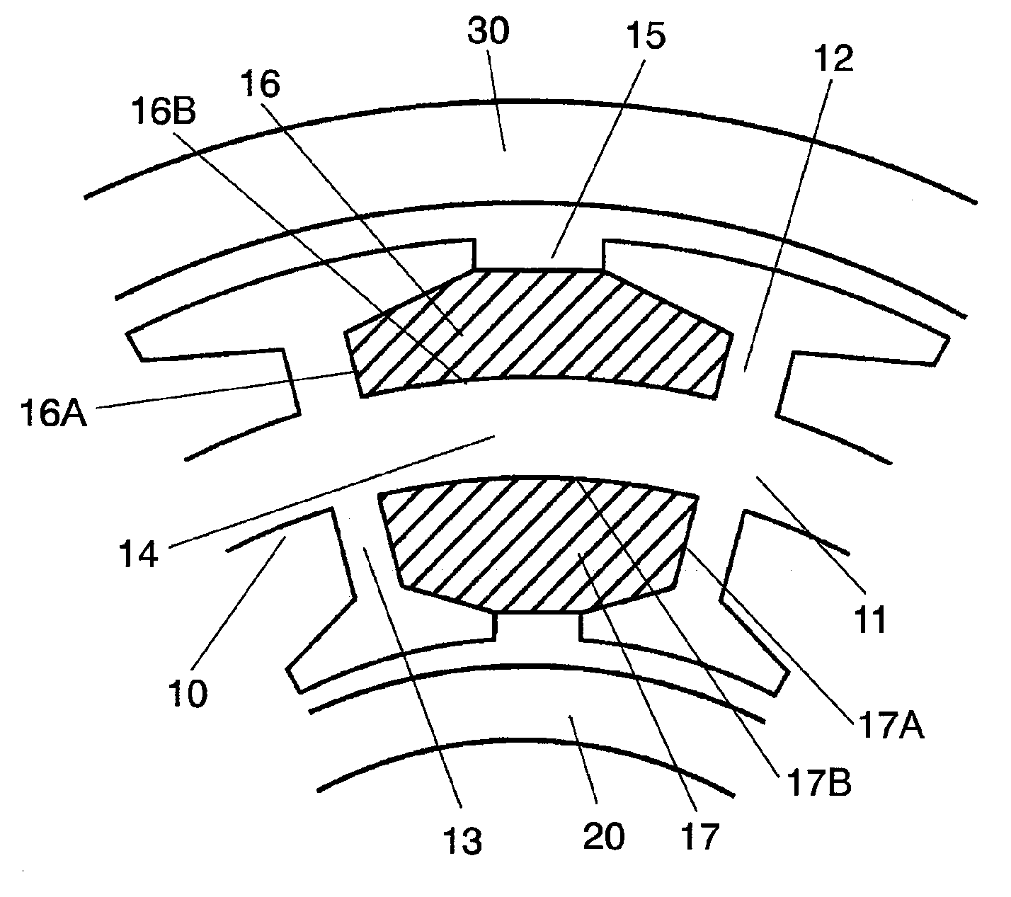
[0040]FIG. 1 shows a cross sectional view in part of a motor in accordance with the first embodiment of the present invention. The motor in accordance with the first embodiment comprises the following elements:[0041]stator 10;[0042]inner rotor 20 confronting an inner wall of stator 10; and[0043]outer rotor 30 confronting an outer wall of stator 10.

[0044]Stator 10 includes stator core 11 which comprises the following elements:[0045]annular stator yoke 14;[0046]outer teeth 12 projecting outward from stator yoke 14 and a plurality of inner teeth 13, in the same number as outer teeth 12, projecting inward from stator yoke 14.

[0047]Outer slots 16 are formed between each one of outer teeth 12, and inner slots 17 are formed between each one of inner teeth 13. A plurality of three-phase windings 15 connected with a star or a delta connection are wound on stator yoke 14 between each one of outer slots 16 and inner slots 17.

[0048]Outer rotor 30 is placed such that it confronts outer teeth 12 ...

embodiment 2

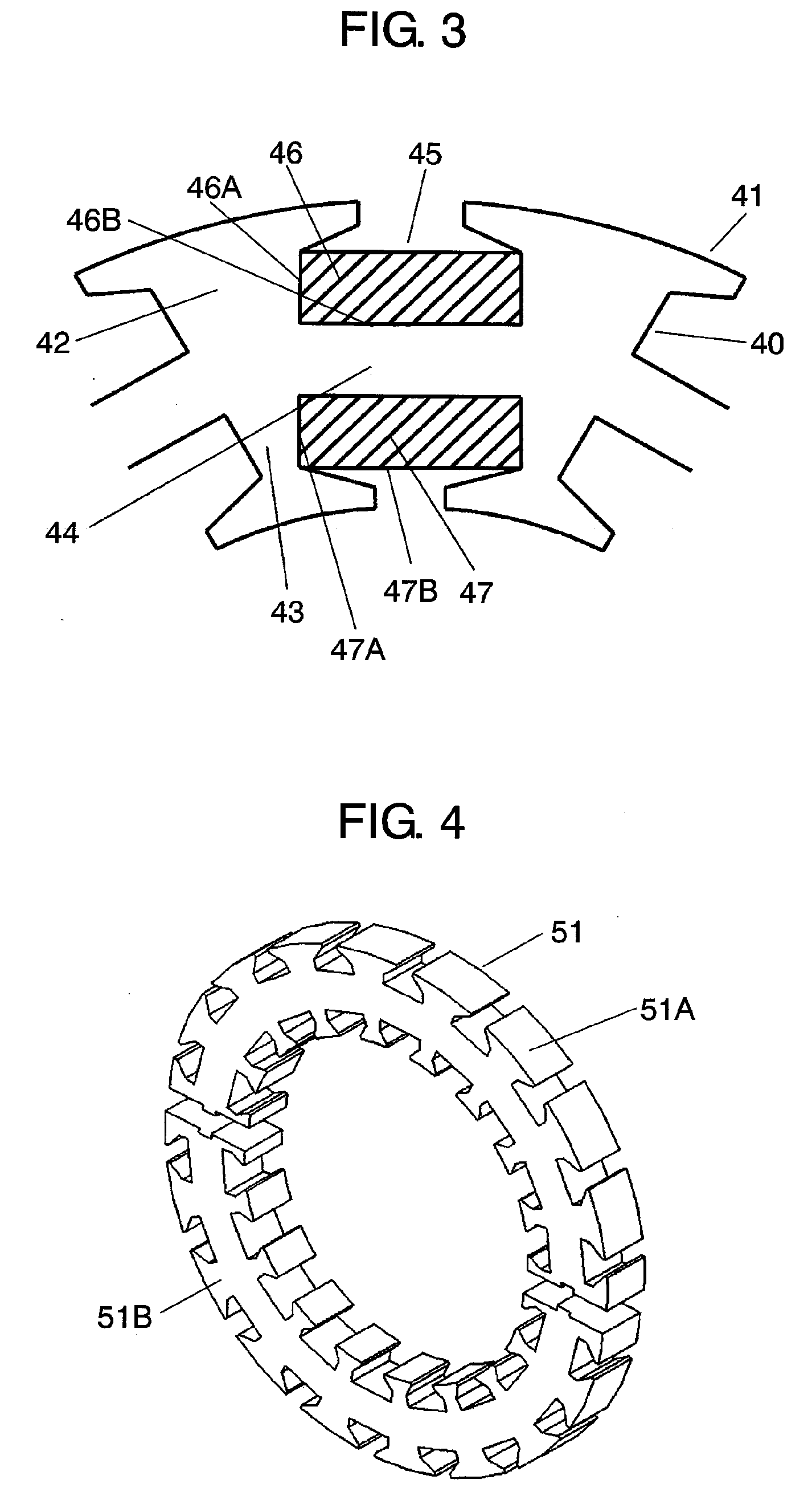
[0053]FIG. 3 shows a cross sectional view of a stator of a motor in accordance with the second embodiment of the present invention. The motor in accordance with the second embodiment comprises the following elements:[0054]stator 40;[0055]an inner rotor (not shown) confronting the inner wall of stator 40; and[0056]an outer rotor (not shown) confronting the outer wall of stator 40.

Since the inner rotor and the outer rotor are the same as those described in the first embodiment, the descriptions thereof are omitted here.

[0057]Stator 40 includes stator core 41 which comprises the following elements:[0058]annular stator yoke 44;[0059]outer teeth 42 projecting outward from stator yoke 44 and a plurality of inner teeth 43, in the same number as the outer teeth, projecting inward from the stator yoke 44.

[0060]Outer slots 46 are formed between each one of outer teeth 42, and inner slots 47 are formed between each one of inner teeth 43. A plurality of three-phase windings 45 connected with a ...

embodiment 3

[0066]FIG. 4 shows a perspective view of a stator core of a motor in accordance with the third embodiment of the present invention. Stator core 51 is split into two units, i.e. core piece 51A and core piece 51B. The split stator cores are jointed together by welding or so on after they are provided with the windings.

[0067]Split of stator core 51 allows increasing the winding efficiency when the stator core is provided with the toroidal windings, so that the number of steps of windings can be reduced and the winding cost can be lowered. Stator core 51 can use the slot shape demonstrated in the first and second embodiments.

[0068]In this embodiment, the stator core is split into two units; however, it can be split into any integer equal to 2 or more than 2 so that the winding efficiency can be increased in relation with a winding machine.


PUM


Abstract

A motor includes a stator which includes a stator core having an annular stator yoke, a plurality of outer teeth projecting outward from the stator yoke and a plurality of inner teeth projecting inward from the stator yoke, and a plurality of windings wound on the stator core. The motor also includes an outer rotor confronting the outer teeth with an air gap therebetween and an inner rotor confronting the inner teeth with an air gap therebetween. This motor thus has twin-rotor. The stator core includes outer slots between each one of the outer teeth as well as inner slots between each one of the inner teeth, and the windings are wound on the stator yoke between the outer slot and the inner slot. A cross sectional cut of the stator reveals that a sectional area of the outer slot is equal to that of the inner slot.

Description

TECHNICAL FIELD[0001]The present invention relates to a motor having twin-rotor, and an apparatus to which the same motor is mounted, more particularly it relates to a structure of a stator core of the motor.BACKGROUND ART[0002]FIG. 6 shows a brushless motor with conventional twin-rotor of toroidal method, and this motor is formed of stator 110, inner rotor 120 and outside rotor 130.[0003]Stator 110 includes stator yoke 114, outer teeth 112 and inner teeth 113 both formed on stator yoke 114. Stator yoke 114 is wound with a plurality of three-phase windings 115 in the toroidal method. In general, windings 115 are connected with a delta connection or a star connection.[0004]Inner rotor 120 is directly connected to shaft 123 and rotatably held inside stator 110. Inner rotor 120 includes rotor yoke 121 and permanent magnets 122. Outer rotor 130 is also connected to shaft 123 and rotatably held outside stator 110. Outer rotor 130 includes rotor yoke 131 and permanent magnets 132. Inner r...

Claims


Application Information

Patent Timeline
IPC IPC(8): H02K23/36
CPCH02K21/12H02K16/02H02K1/06H02K1/16H02K3/28
Inventor YOSHIKAWA, YUICHIKOSHIBA, ATSUYOSHILI, HUMORISAKI, MASAHIKOMURAKAMI, HIROSHI
Owner PANASONIC CORP
Why Eureka
Try Eureka