
Linear antenna array with azimuth beam augmentation by axial rotation

a technology of axial rotation and antenna array, applied in antennas, antenna details, electrical devices, etc., can solve the problems of severe constraints on the tolerance and accuracy of mechanical phase shifters

Inactive Publication Date: 2009-05-28
INTEL CORP
View PDF18 Cites 38 Cited by
  • Summary
  • Abstract
  • Description
  • Claims
  • Application Information

AI Technical Summary

Benefits of technology

[0007]In a first aspect the present invention provides an antenna for a wireless network, comprising a first reflector having a first plurality of radiators coupled thereto and a second reflector having a second plurality of radiators coupled thereto, wherein the first and second pl

Problems solved by technology

This places severe constraints on the tolerance and accuracy of a mechanical phase shifter to provide the required signal division between various radiating elements over various azimuth beam width settings.

Method used


Image

  • Linear antenna array with azimuth beam augmentation by axial rotation
  • Linear antenna array with azimuth beam augmentation by axial rotation
  • Linear antenna array with azimuth beam augmentation by axial rotation

Examples


Embodiment Construction

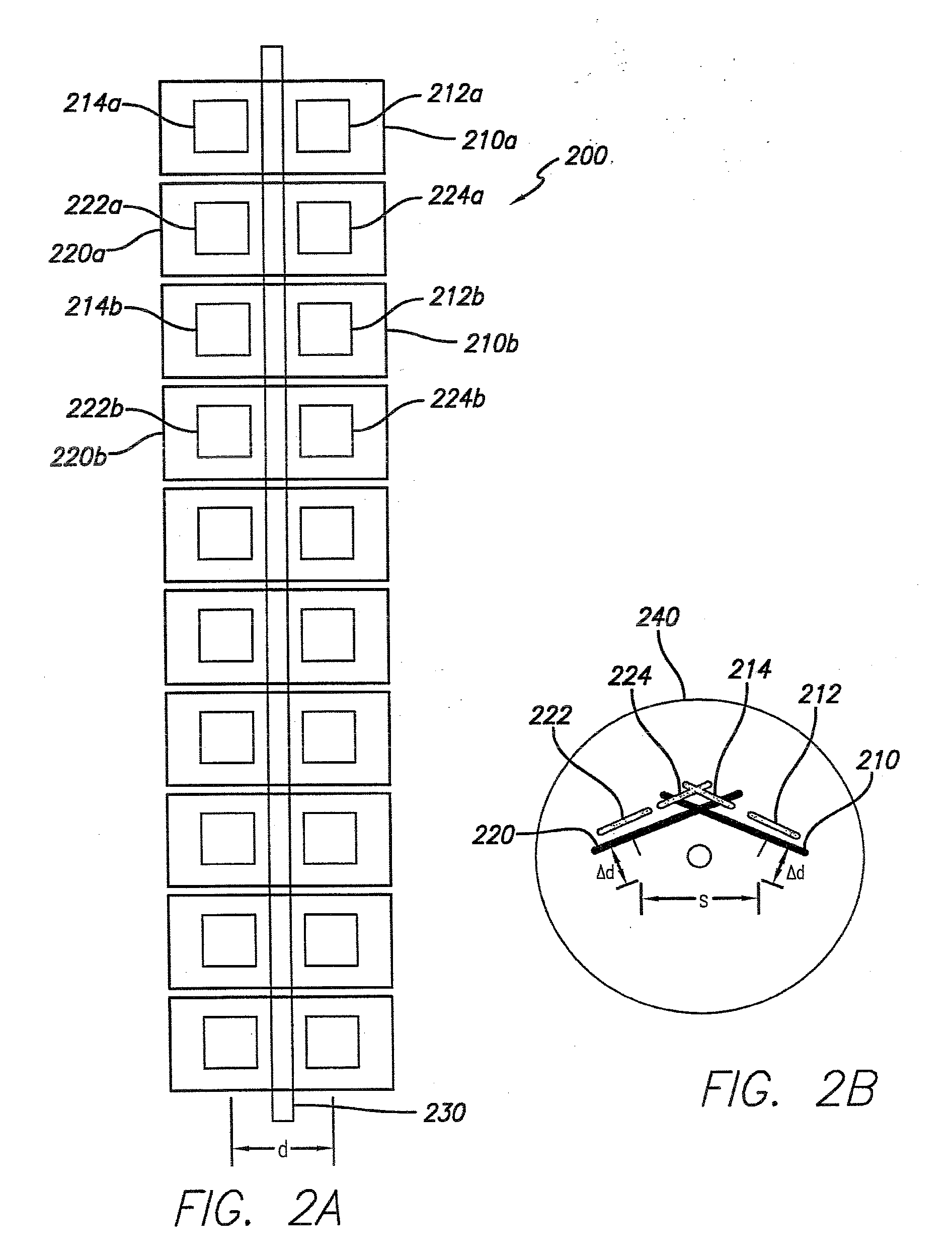
[0019]The present invention provides an antenna array with mechanical azimuth beam width control. In the illustrated embodiments beam width can be continuously augmented through on-axis rotation of a single-column or a dual-column linear array.

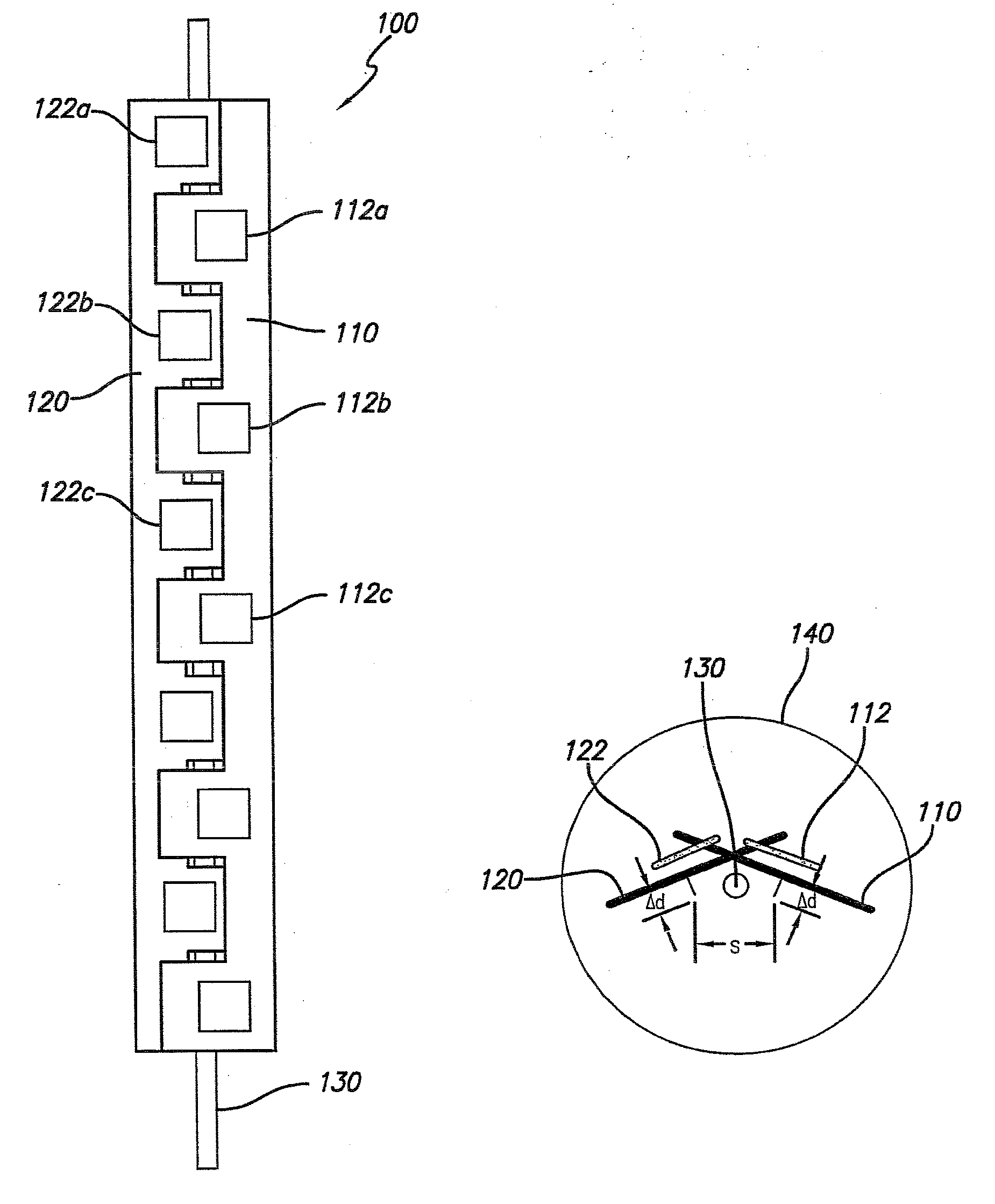
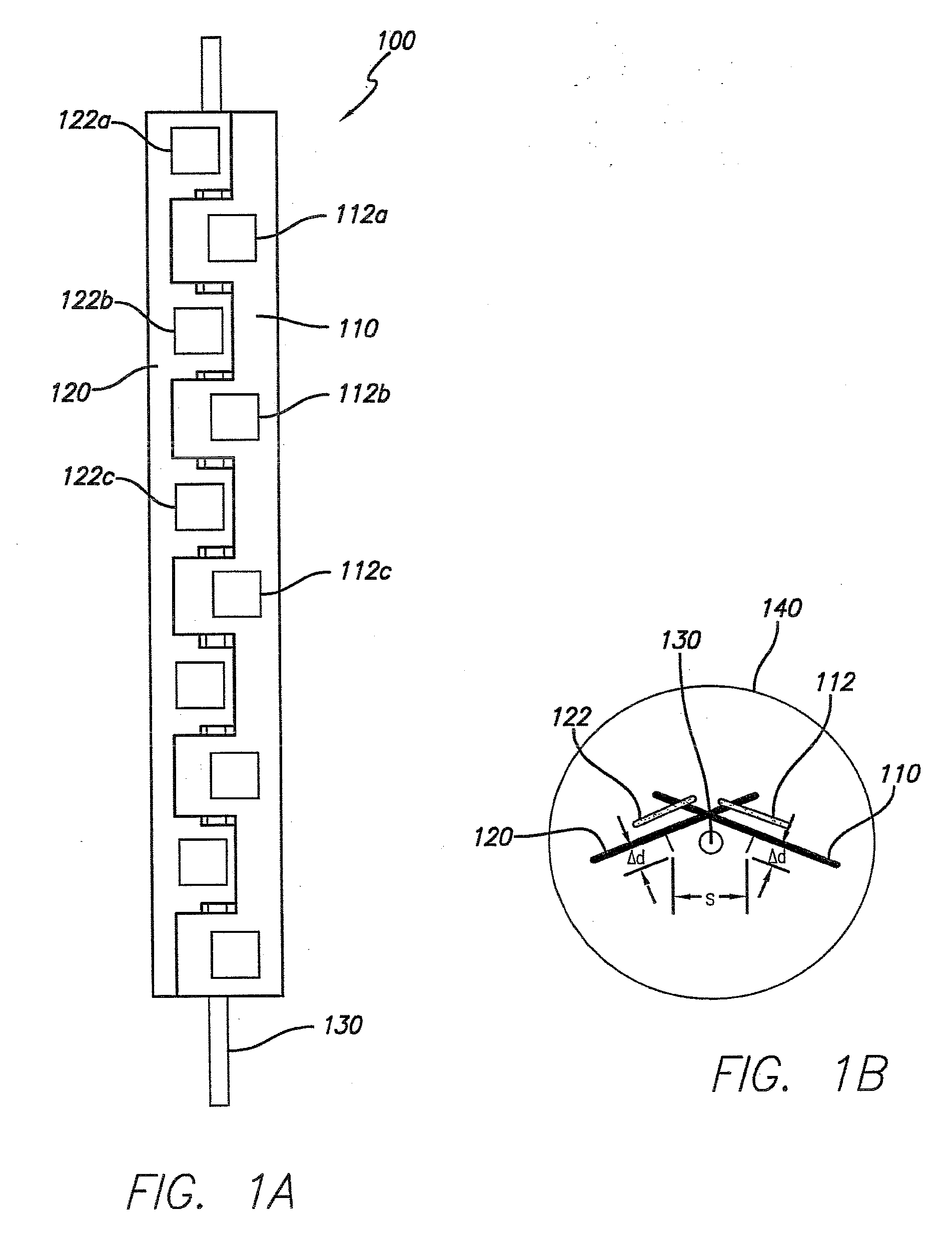
[0020]FIGS. 1A and 1B show the single-column embodiment of the present invention in front and top views, respectively. The antenna array 100 includes a first reflector 110 and a second reflector 120 movably mounted for rotational movement, for example about a mounting rod 130. Various actuation mechanisms are possible and for example may couple to the reflector panels at the top and / or bottom of the reflector panels to effect rotation of the panels in opposite angular directions in the azimuth. For example, the teachings of U.S. provisional patent application Ser. No. 61 / 004,242 filed Nov. 26, 2007 may be employed for the actuation mechanism and coupling to the panels, the disclosure of which is incorporated herein by reference in its entirety...


PUM


Abstract

An antenna array with azimuth beam width that can be continuously augmented through on-axis rotation of a single-column or a dual-column linear array is disclosed. Alternate radiating elements in the vertical direction are arranged on separate reflectors which are movable to change their angle in the azimuth to alter beam width.

Description

RELATED APPLICATION INFORMATION[0001]The present application claims priority under 35 USC section 119(e) to U.S. provisional patent application Ser. No. 61 / 004,525 filed Nov. 28, 2007, the disclosure of which is incorporated herein by reference in its entirety.BACKGROUND OF THE INVENTION[0002]1. Field of the Invention[0003]The present invention relates in general to communication systems and components. More particularly the present invention is directed to antennas and antenna arrays employed in wireless communications systems.[0004]2. Description of the Prior Art and Related Background Information[0005]Modern wireless antenna implementations generally include a plurality of radiating elements that may be arranged over a ground plane defining a radiated (and received) signal beam width and azimuth scan angle. Azimuth antenna beam width can be advantageously modified by varying amplitude and phase of an RF signal applied to respective radiating elements. Azimuth antenna beam width h...

Claims


Application Information

Patent Timeline
IPC IPC(8): H01Q19/18H01Q21/00
CPCH01Q1/246H01Q21/08H01Q3/06
Inventor FOO, SENGLEE
Owner INTEL CORP
Learn More