Resolution radar using metamaterials

a technology of metamaterials and radars, applied in the field of antenna systems, can solve the problems of reducing the resolution of the above-mentioned limit, unable to use the “near-field” component of the radiated field, and not enhancing the near-field component of the wave, so as to achieve the effect of improving resolution and resolution

Active Publication Date: 2009-05-28
NORTHROP GRUMMAN SYST CORP
View PDF14 Cites 50 Cited by
  • Summary
  • Abstract
  • Description
  • Claims
  • Application Information

AI Technical Summary

Benefits of technology

[0037]In another embodiment, by partially overlapping the focal points of the transmit and receive lenses, the resolution may be improved, but at the expense of received power. As an example, if a transmit lens and a receive lens each have a focal point that is ten meters wide, and the focal point of the receive lens overlaps only two meters of the transmit lens focal point, the resolution is improved at the expense of received power, depending upon the focal point pattern. This is not an issue for close-in applications with significantly concentrated transmit power.

Problems solved by technology

This limitation is the result of diffraction that takes place because of the wave nature of electromagnetic radiation.
Moreover, it should be noted that the resolution limit described above arises from the assumption that the image of an object is being detected in the “far-field”, that is, a distance at which the far-field dominates over all other aspects of the electromagnetic radiation.
Conventional far-field imaging techniques are unable to use the “near-field” component of the radiated field.
However, both of these references suffers from one or more of the following disadvantages: not enhancing the near-field component of the wave, not using near-field probes, not using sub-wavelength illumination, not utilizing for metal penetration, and not detecting the near-field of the source or object to be imaged.

Method used


Image

  • Resolution radar using metamaterials
  • Resolution radar using metamaterials
  • Resolution radar using metamaterials

Examples


Embodiment Construction

is hereafter described with specific reference being made to the drawings.

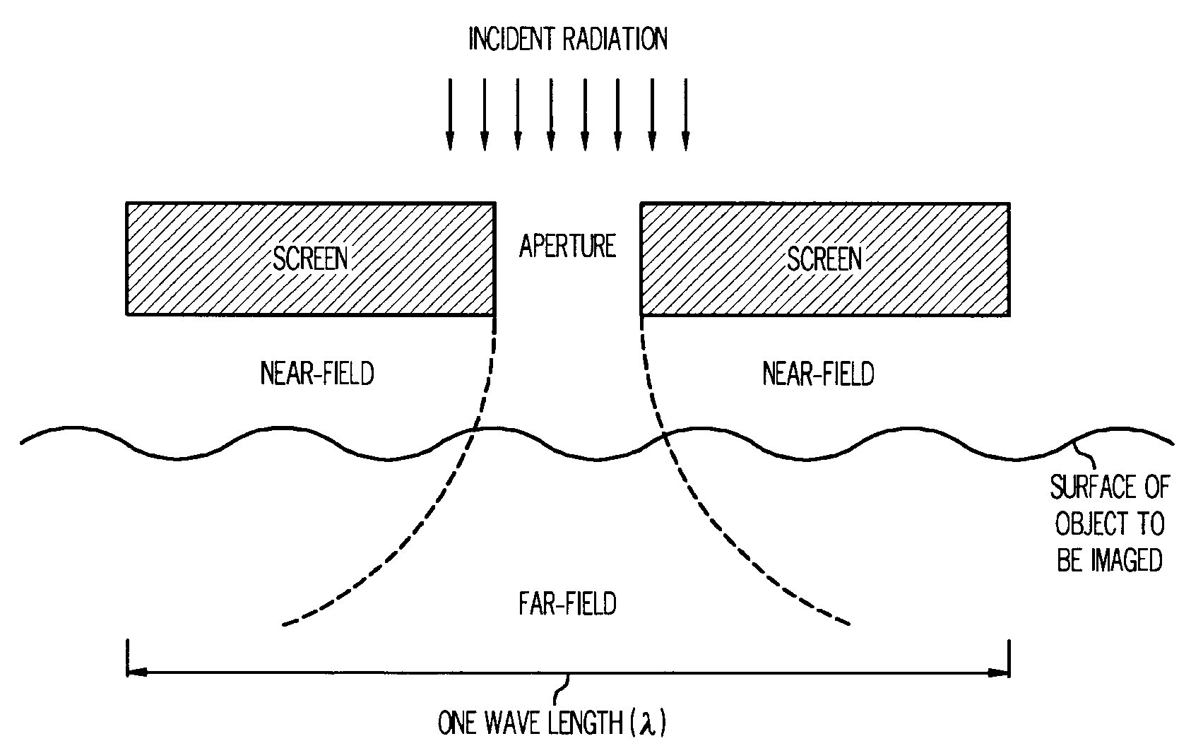
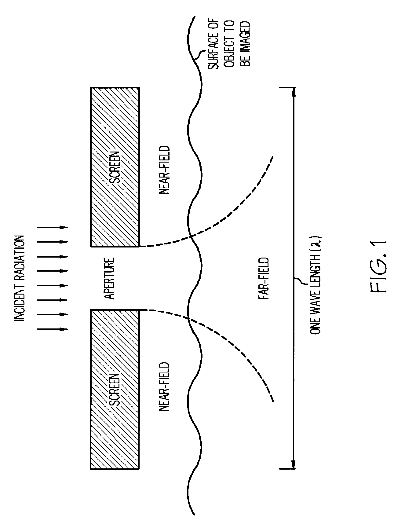
[0043]FIG. 1 is a schematic representation of the near-field diffraction from a subwavelength aperture.

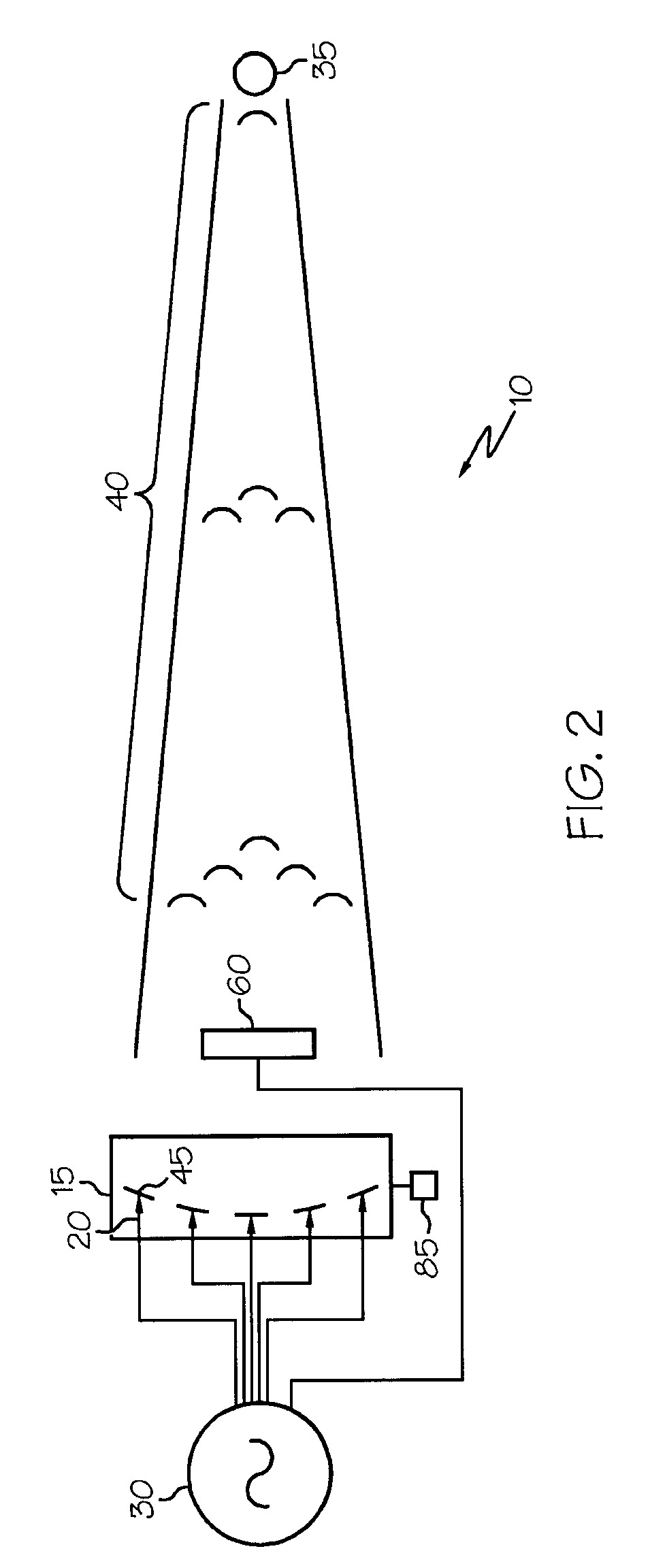
[0044]FIG. 2 is a block diagram of an embodiment of the present invention depicting sub-wavelength illumination using a metamaterial transmit array.

[0045]FIG. 3 is a block diagram of an embodiment of the present invention depicting sub-wavelength illumination and detection using metamaterial transmit and receive arrays.

[0046]FIG. 4 is a block diagram of an embodiment of the present invention using amplitude discrimination circuitry.

[0047]FIG. 5 is a block diagram of an embodiment of control, conditioning, and processing circuitry of the present invention.

[0048]FIG. 6 is a graphical representations of a transmit array focal point and a receive array focal point partially overlapping.

DETAILED DESCRIPTION

[0049]While this invention may be embodied in many different forms, there are described in detail herein spec...


PUM


Abstract

A radar system includes at least one transmit array comprising a plurality of metamaterial elements. The radar system further includes at least one near-field stimulator for inputting electromagnetic signal to the transmit array so that a sub-wavelength target is illuminated with an electromagnetic wave.

Description

CROSS-REFERENCE TO RELATED APPLICATIONS[0001]Not ApplicableSTATEMENT REGARDING FEDERALLY SPONSORED RESEARCH[0002]Not ApplicableBACKGROUND[0003]1. Field[0004]The invention relates to antenna systems and in particular to antenna systems used in radar applications.[0005]2. Description of the Related Art[0006]The resolution of all lens-based instruments is defined by the finite dimensions of the electromagnetic wave used by a lens. The resolving power, or the minimum separation between two points which can be resolved (dmin), can be approximated by λ / 2, where λ is the wavelength of light. This limitation is the result of diffraction that takes place because of the wave nature of electromagnetic radiation. Moreover, it should be noted that the resolution limit described above arises from the assumption that the image of an object is being detected in the “far-field”, that is, a distance at which the far-field dominates over all other aspects of the electromagnetic radiation. For these re...

Claims


Application Information

Patent Timeline
Patent Type & Authority Applications(United States)
IPC IPC(8): H01Q15/02
CPCF41H13/00H01P1/20G01S13/885G01S7/414H01Q15/0086H01Q15/10
Inventor FULLER, CHRISTOPHERLAMBERG, JOHN R.
Owner NORTHROP GRUMMAN SYST CORP
Why Eureka
Try Eureka