Led Lamp

a technology of led lamps and led tubes, applied in the direction of discharge tubes luminescnet screens, semiconductor devices for light sources, lighting and heating apparatus, etc., can solve the problems of white light, color unevenness will be produced inevitably, easy to produce color unevenness, etc., to reduce glare, reduce glare, and reduce glare

Inactive Publication Date: 2009-05-28
SOVEREIGN PEAK VENTURES LLC
View PDF21 Cites 46 Cited by
  • Summary
  • Abstract
  • Description
  • Claims
  • Application Information

AI Technical Summary

Benefits of technology

[0024]In an LED lamp according to the present invention, at least a part of the side surface portion of a light-transmissive member that covers an LED chip has lower transmittance than the upper surface portion thereof, thus controlling the emission of light through the side surface portion that easily causes the glare. As a result, the LED lamp of the present invention can minimize the glare effectively.

Problems solved by technology

An LED lamp of this type, however, easily produces color unevenness because the LED chip of each color has an excellent monochromatic peak.
That is to say, unless the light rays emitted from the respective LED chips are mixed together uniformly, color unevenness will be produced inevitably in the resultant white light.

Method used


Image

  • Led Lamp
  • Led Lamp
  • Led Lamp

Examples


embodiment 1

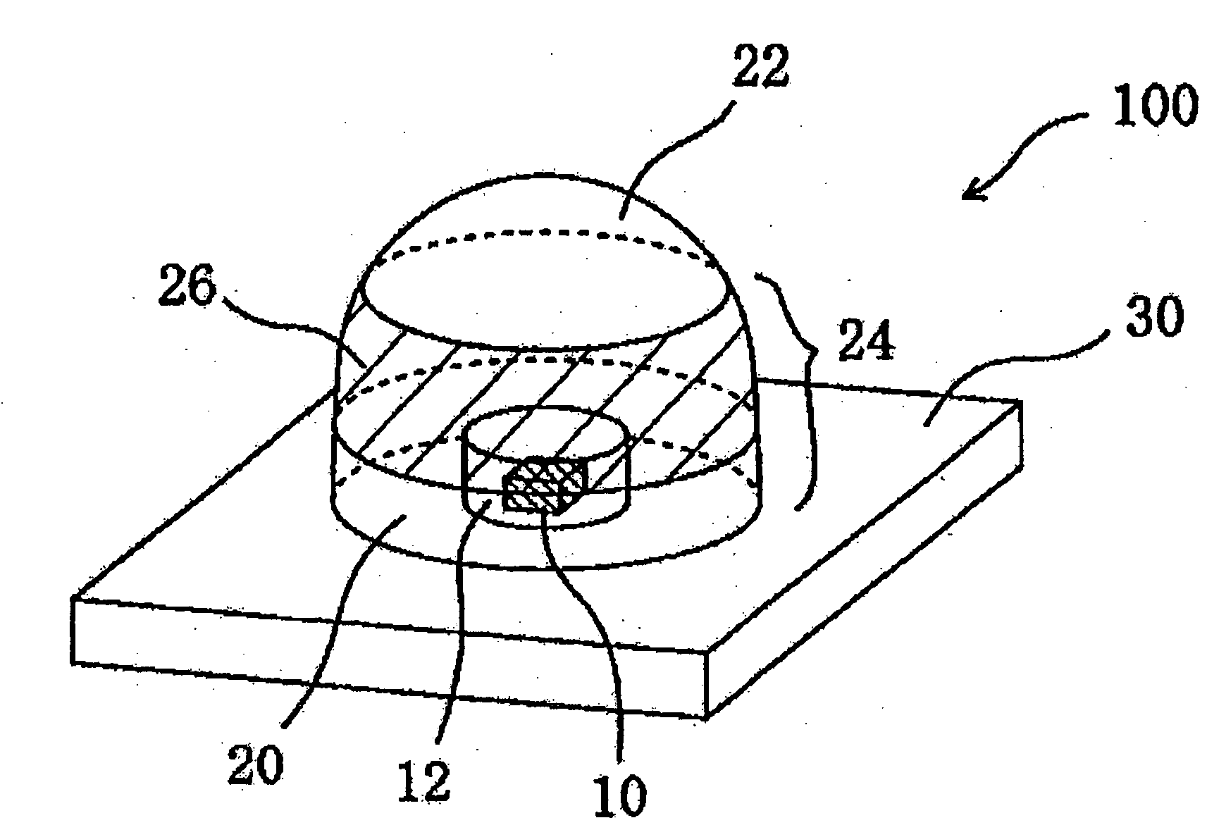
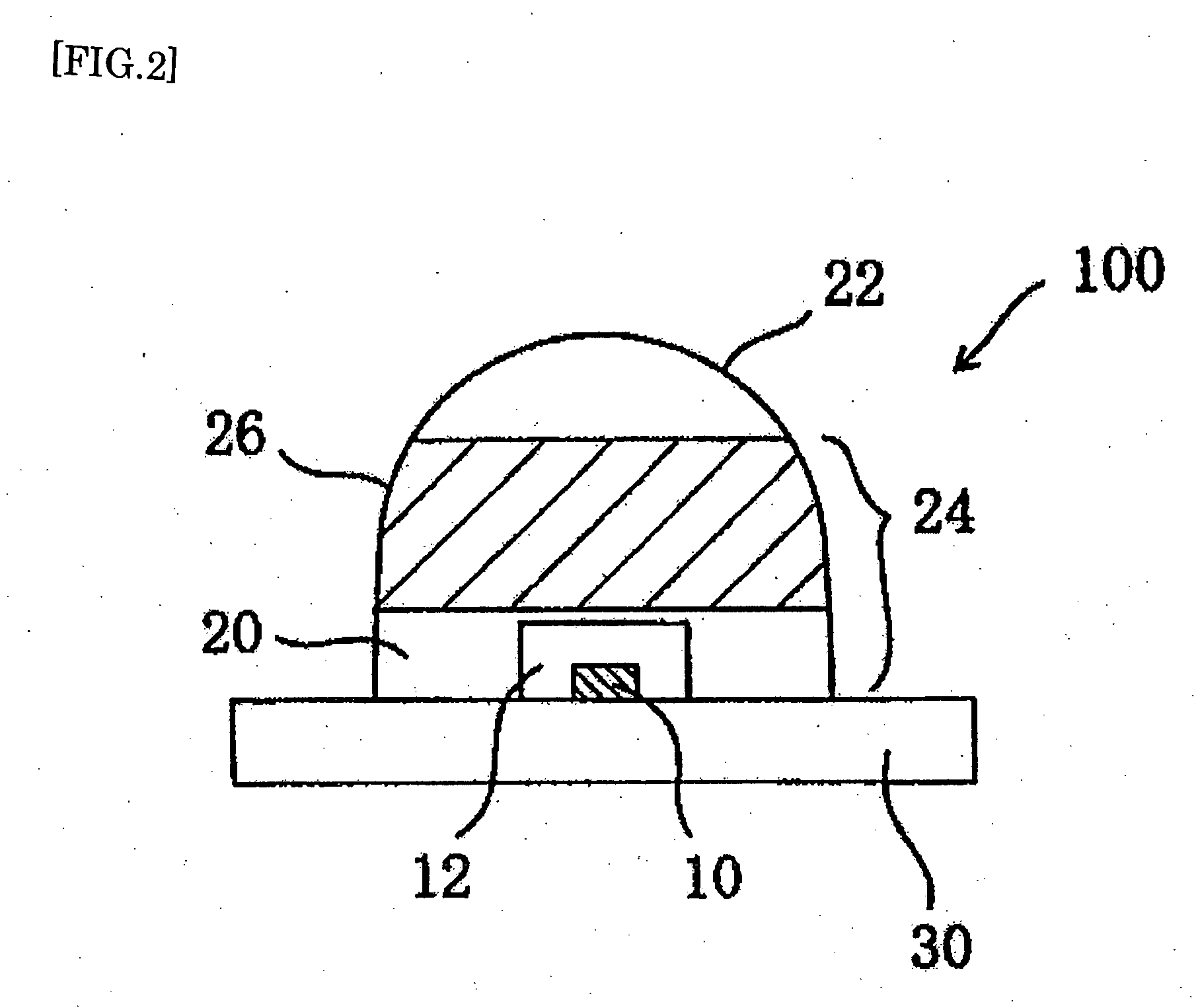
[0070]First, a first specific preferred embodiment of an LED lamp according to the present invention will be described with reference to FIGS. 2 and 3. FIG. 2 is a cross-sectional view schematically illustrating the configuration of an LED lamp 100 according to this preferred embodiment. FIG. 3 is a perspective view thereof.

[0071]The LED lamp 100 includes an LED chip 10, a phosphor resin portion 12 that covers the LED chip 10, and a light-transmissive member 20 that covers the phosphor resin portion 12.

[0072]The phosphor resin portion 12 includes a phosphor for converting the emission of the LED chip 10 into light that has a longer wavelength than the emission and a resin in which the phosphor is dispersed.

[0073]The light-transmissive member 20 has the function of shutting off (or encapsulating) the phosphor resin portion 12 from the air and may be formed by molding a resin, glass or any other suitable material. In this preferred embodiment, the light-transmissive member 20 is made ...

embodiment 2

[0108]Hereinafter, a preferred embodiment of an LED lamp, of which the light-transmissive member 20 has a flat upper surface portion 22, will be described. FIG. 13 is a cross-sectional view of an LED lamp 100 according to this preferred embodiment and FIG. 14 is perspective view of the LED lamp 100.

[0109]In this preferred embodiment, the light-transmissive member 20 has a substantially trapezoidal cross section as viewed on a plane that is perpendicular to the principal surface of the substrate 30 as shown in FIGS. 13 and 14. As in the preferred embodiment described above, a part of the side surface portion 24 of the light-transmissive member 20 is the low-transmittance part 26. Thus, the emission of the LED lamp 100 can be effectively directed toward the direction that is perpendicular to the substrate 30 (with an angle of radiation θ=0 degrees) and the glare can be reduced as a result.

[0110]In this preferred embodiment, a part of the side surface portion 24 of the light-transmissi...

embodiment 3

[0111]If an LED lamp 100 according to any of various preferred embodiments described above is used as a downlight, one of the embodiments shown in FIGS. 16, 17 and 18 may be adopted, for example. In each of these examples, the LED lamp 100 is a card LED lamp. FIG. 16 illustrates an exemplary configuration for a desk lamp. FIG. 17 illustrates an exemplary configuration that can be used as a replacement for a straight-tube fluorescent lamp. And FIG. 18 illustrates an exemplary configuration that can be used as a replacement for a circular-tube fluorescent lamp.

[0112]In the example illustrated in FIG. 16, the card LED lamp 100 is set by being inserted into a receptacle portion 164, which is provided for its body portion 160, so as to get ready to turn ON.

[0113]On the other hand, in the examples illustrated in FIGS. 17 and 18, the card LED lamp 100 is set through a slot 65, which has been cut through their body portion 60, and gets ready to turn ON. The body portion 60 is connected to a...


PUM


Abstract

An LED lamp 100 includes: an LED chip 10; a phosphor resin portion 12 that covers the LED chip 10; and a light-transmissive member 20 that covers the phosphor resin portion 12. The phosphor resin portion 12 includes: a phosphor for converting the emission of the LED chip 10 into light that has a longer wavelength than the emission; and a resin in which the phosphor is dispersed. The surface of the light-transmissive member 20 includes an upper surface portion 22 located over the LED chip 10 and a side surface portion 24 located around and below the upper surface portion 22. At least a part (low-transmittance part 26) of the side surface portion 24 of the light-transmissive member 20 has lower transmittance than the upper surface portion 22.

Description

TECHNICAL FIELD[0001]The present invention relates to an LED lamp and more particularly relates to an LED lamp that can be used effectively as a white light source for general illumination.BACKGROUND ART[0002]A light emitting diode (which will be referred to herein as an “LED chip”) is a semiconductor device that can radiate an emission in a bright color with high efficiency even though its size is small. The emission of an LED chip has an excellent monochromatic peak. To produce white light from LED chips, a conventional LED lamp arranges red, green and blue LED chips close to each other and gets the light rays in those three different colors diffused and mixed together. An LED lamp of this type, however, easily produces color unevenness because the LED chip of each color has an excellent monochromatic peak. That is to say, unless the light rays emitted from the respective LED chips are mixed together uniformly, color unevenness will be produced inevitably in the resultant white li...

Claims


Application Information

Patent Timeline
Patent Type & Authority Applications(United States)
IPC IPC(8): F21V13/02F21V7/00F21V9/16H01L33/50F21S2/00F21V5/00H01L33/60
CPCF21V19/001F21Y2101/02H01L33/54H01L33/52H01L33/44F21Y2115/10H01L2224/48091H01L2224/48247H01L2224/48257H01L2224/49107H01L2224/8592H01L2924/181H01L2924/00012H01L2924/00014
Inventor YANO, TADASHISHIMIZU, MASANORITAKAHASHI, KIYOSHI
Owner SOVEREIGN PEAK VENTURES LLC
Why Eureka
Try Eureka