Manipulation device for loading and unloading a shelf

a technology for manipulating devices and shelves, applied in the direction of lifting devices, bearings, items transportation vehicles, etc., can solve the problems of excessively large number of metal chips, and achieve the effects of high stability, simple manufacturing, and large lifting distan

Inactive Publication Date: 2009-05-28
MUSER MIGUEL
View PDF9 Cites 37 Cited by
  • Summary
  • Abstract
  • Description
  • Claims
  • Application Information

AI Technical Summary

Benefits of technology

[0010]The object of the invention is to avoid the cited disadvantages and provide a manipulation device which may be manufactured with little production expenditure.
[0012]To be able to absorb high forces, it is advantageous if the lift truck has two first linear roller bearing units situated one above another on each side, which are guided in corresponding second profiled rails of the first telescoping part situated one above another.
[0013]Especially simple production results if the lift truck has a girder part on each side, on which the linear roller bearing units and support rolls are attached.
[0016]To allow large lifting distances in both extension directions with high stability, it is advantageous if the first linear roller bearing units are situated approximately in the area of a central plane of the lift truck situated perpendicularly to the displacement direction.
[0017]A space-saving and simple drive of the first telescoping part is made possible if at least a first telescoping part has a toothed rack, in which a drive gearwheel mounted so it is rotatable on the girder part engages. It is especially advantageous if the first telescoping part has an endless traction means, which is connected in areas spaced apart equally from one another on the traction means to the lift truck, preferably to the girder part, and to the second telescoping part. Both the first and also the second telescoping part may thus be driven simultaneously using the drive gearwheel.

Problems solved by technology

Upon use in processing centers, the problem additionally results that an extremely large number of metal chips occur, because of which special skimming systems are necessary.

Method used


Image

  • Manipulation device for loading and unloading a shelf
  • Manipulation device for loading and unloading a shelf
  • Manipulation device for loading and unloading a shelf

Examples


Embodiment Construction

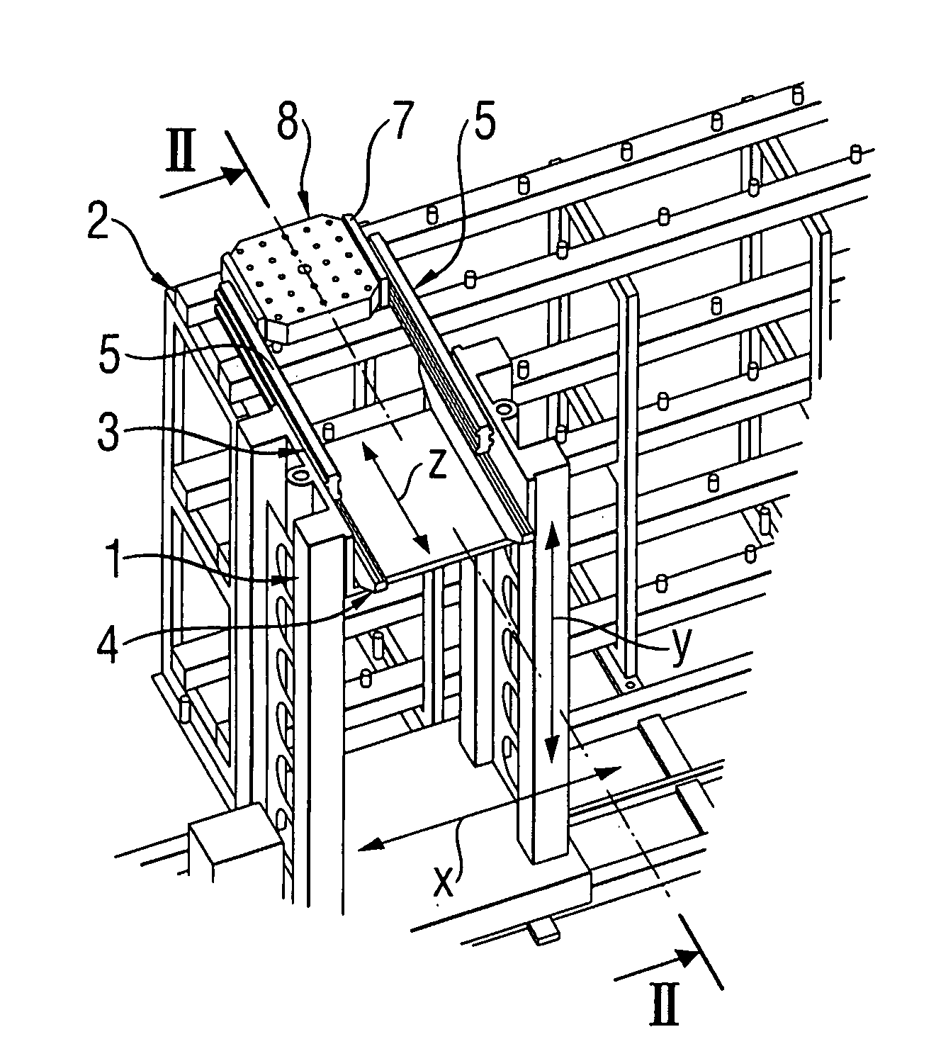
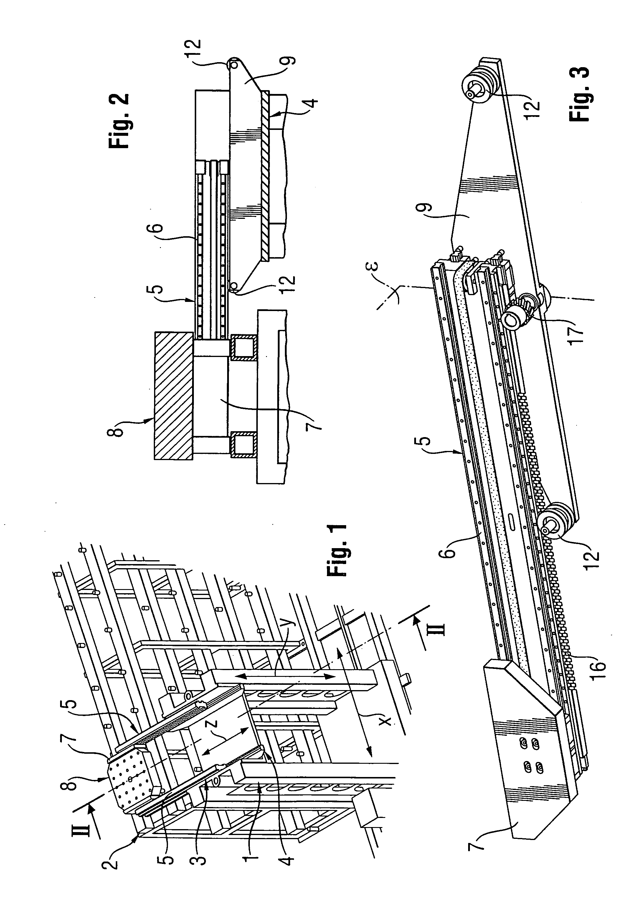
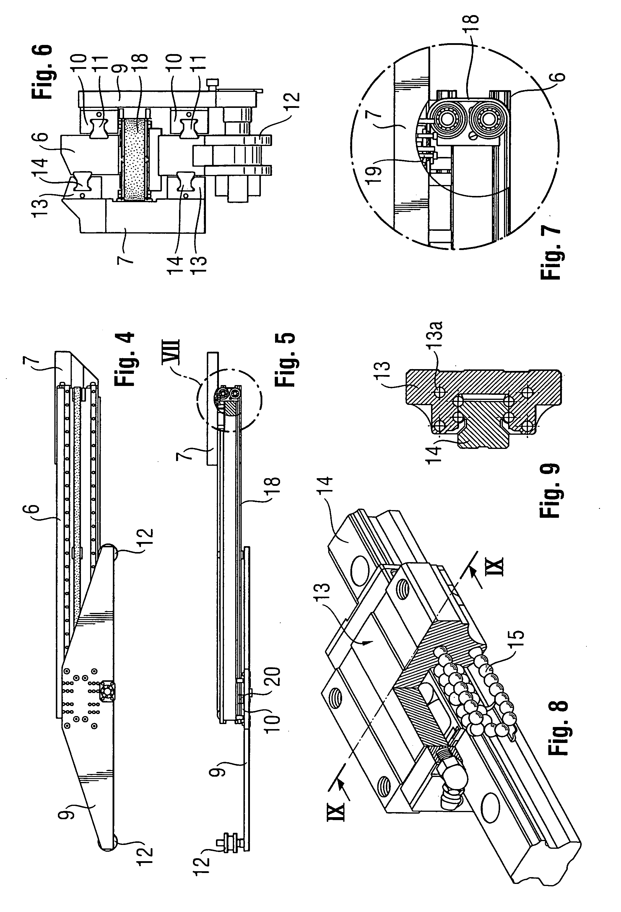
[0028]The manipulation device 1 for loading and unloading a shelf 2 is movable in the directions x, y, and z. For the movement in the z direction, the manipulation device 1 has a truck unit 3 having a lift truck 4 and two laterally situated telescopic extensions 5. Each telescopic extension 5 comprises a first telescoping part 6 and a second telescoping part 7, a palette 8 being able to be accommodated between the two second telescoping parts 7. The accommodation of the palette 8 may be performed by lifting from below or by lateral engagement on a palette 8 by lateral telescoping forks or the like. The lift truck 4, which may be moved in the vertical lifting direction y via a mechanism (not shown in greater detail), has a support part 9 on each side parallel to the displacement direction z, on which two first linear roller bearing units 10 are situated one above another in the area of a central plane E perpendicular to the displacement direction z in each case. The two first linear ...


PUM


Abstract

The invention relates to a manipulation device for loading and unloading a shelf, in particular for a processing center, having at least one lift truck including a telescopic extension, the telescopic extension having at least one first telescoping part and at least one second telescoping part, and the first telescoping part being connected to the lift truck and the second telescoping part being connected to the first telescoping part so it is displaceable in an essentially horizontal displacement direction. To reduce the manufacturing expenditure, it is provided that the lift truck has at least one first linear roller bearing unit and at least one support roll, spaced apart from the first linear roller bearing unit in the displacement direction, in the area of sides parallel to the displacement direction, and each first telescoping part has at least one first profiled rail situated parallel to the displacement direction, each first linear roller bearing unit being guided in a first profiled rail, and the first telescoping parts being supported by the support rolls of the lift truck.

Description

BACKGROUND OF THE INVENTION[0001]The invention relates to a manipulation device for loading and unloading a shelf, in particular for a processing center, having at least one lift truck comprising a telescopic extension, the telescopic extension having at least one first telescoping part and at least one second telescoping part, and the first telescoping part being connected to the lift truck and the second telescoping part being connected to the first telescoping part so it is displaceable in an essentially horizontal displacement direction.DESCRIPTION OF THE PRIOR ART[0002]A device for the transverse movement of a load receiving means in an overhead system for operating storage units is known from WO 03 / 040021 A1, which comprises a horizontally displaceable stage, on which telescopically interlocking pushing elements are implemented in such a way that an overall size is provided in a first state which essentially corresponds to the overall size of the largest pushing element. In th...

Claims


Application Information

Patent Timeline
Patent Type & Authority Applications(United States)
IPC IPC(8): B60P1/52B60P3/14
CPCB65G1/0407B66F9/07F16C29/0635F16C29/008B66F9/141
Inventor MUSER, MIGUEL
Owner MUSER MIGUEL
Why Eureka
Try Eureka