Fuel cell system and control method thereof

a fuel cell and system technology, applied in the field of fuel cell systems, can solve the problems of extreme large amount of anode off-gas exhausted in a short time, and achieve the effects of ensuring the power generation performance of the fuel cell, increasing the total replacement amount of gas, and reducing the effective power generation area

Inactive Publication Date: 2009-05-28
HONDA MOTOR CO LTD
View PDF3 Cites 7 Cited by
  • Summary
  • Abstract
  • Description
  • Claims
  • Application Information

AI Technical Summary

Benefits of technology

[0025]Accordingly, the pressure of dilution gas to be introduced from the inlet pipe to the retention chamber decreases in the case of performing low temperature startup on the fuel cell, as compared with the case of performing normal startup. This leads to a reduction in the flow per unit time of anode off-gas to be evacuated from the retention chamber to the dilution gas pipe or the concentration of anode off-gas in gas to be exhausted from the dilution means. Accordingly, the total replacing amount of gas can be increased by replacing gas retained in the fuel cell for a longer time, as compared with the case of performing normal startup. This makes it possible to ensure power generation performance of the fuel cell by using a reactive area effectively, for example, even if residual water freezes in the fuel cell, thereby decreasing the effective power generation area.
[0026]In addition, electric power to be consumed by a means supplying this dilution gas, which is the cathode gas supply means supplying cathode gas, can be reduced by reducing the pressure of dilution gas. Especially, since such replacing of anode gas is conducted when starting up the fuel cell, or before the fuel cell begins electric power generation, the electric power to be consumed by the cathode gas supply means is supplied from a battery. Thus, according to the present invention, by suppressing consumption of battery power, unconsumed battery power can be used as electric power energy for operating other accessories such as an air conditioner and the like, and also a smaller and cheaper battery can be used.
[0027]According to the fuel cell system of the present invention, the total replacing amount of gas increases in the case of performing low temperature startup on the fuel cell, as compared with the case of performing normal startup. This makes it possible to ensure power generation performance of the fuel cell by using a reactive area effectively, for example, even if residual water freezes in the fuel cell, thereby decreasing and the effective power generation area. In addition, it is possible to decrease the amount of anode off-gas to be exhausted per a unit time increasing the total replacing amount of gas, and decreasing the pressure of anode gas as described above. Accordingly, for the fuel cell system with the diluter, it is no longer necessary to increase the size of the diluter according to the exhaust amount of anode off-gas during low temperature startup.

Problems solved by technology

However, in the fuel cell system disclosed in the abovementioned patent application, the supply pressure and the flow of anode gas increase upon low temperature start, whereby an extremely large amount of anode off-gas is exhausted in a short time.

Method used


Image

  • Fuel cell system and control method thereof
  • Fuel cell system and control method thereof
  • Fuel cell system and control method thereof

Examples


Embodiment Construction

[0033]One embodiment of the present invention is described hereinafter with reference to the accompanying drawings.

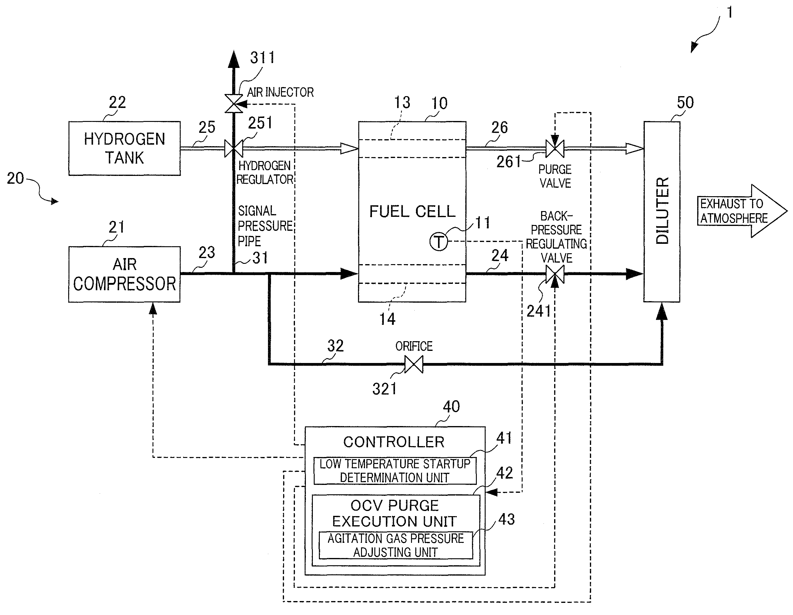
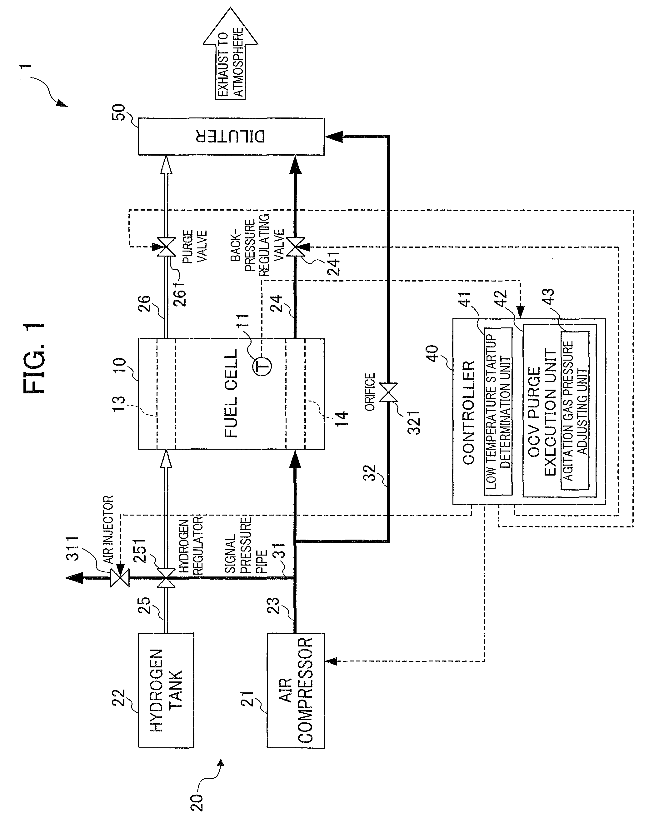
[0034]FIG. 1 is a schematic diagram of the fuel cell system 1 according to the present embodiment. The fuel cell system 1 has a fuel cell 10, a supply device 20 supplying hydrogen gas (hereinafter referred to as “anode gas”) and air (hereinafter referred to as “cathode gas”) to the fuel cell 10, and a control device 40 controlling the fuel cell 10 and the supply device 20.

[0035]The fuel cell 10 has a stack structure in which tens to hundreds of cells are stacked, for example. Each of the cells has a membrane electrode assembly (MEA) sandwiched by a pair of separators. The MEA is configured with two electrodes, an anode (a positive electrode) and a cathode (a negative electrode), and a solid polymer electrolyte membrane sandwiched between these electrodes. Typically, each of the electrodes consists of a catalyst layer in contact with the solid high-polymer electrolyte me...


PUM

PropertyMeasurementUnit
temperatureaaaaaaaaaa
electric poweraaaaaaaaaa
temperatureaaaaaaaaaa

Abstract

An object of the present invention is to provide a fuel cell system capable of starting below freezing point without increasing the size of the diluter. The fuel cell system 1 comprises an OCV purge execution unit 42 replacing gas retained in a fuel cell 10 by supplying additional anode gas from a supply device 20 to the fuel cell 10 when starting up the fuel cell. In addition, the fuel cell system 1 comprises a low temperature startup determination unit 41 determining whether to perform low temperature startup or normal startup on the fuel cell 10. The OCV purge execution unit 42 decreases the pressure of additional anode gas supplied from the supply device 20 and increases the total replacing amount of gas retained in the fuel cell 10 in a case of performing low temperature startup, as compared with a case of performing normal startup.

Description

[0001]This application is based on and claims the benefit of priority from Japanese Patent Application No. 2007-304498, filed on 26 Nov. 2007, the content of which is incorporated herein by reference.BACKGROUND OF THE INVENTION[0002]1. Field of the Invention[0003]The present invention relates to a fuel cell system. Specifically, the present invention relates to a fuel cell system in which the total replacing amount of gas during the OCV purge increases during low temperature startup, as compared with during normal startup.[0004]2. Related Art[0005]In recent years, fuel cell systems have gained the spotlight as a new power source for automobiles. For example, a fuel cell system is provided with a fuel cell producing electric power from chemical reactions of reactive gas, a reactive gas supply device supplying the reactive gas to the fuel cell through a reactive gas channel, and a control device controlling the reactive gas supply device.[0006]For example, the fuel cell consists of a ...

Claims


Application Information

Patent Timeline
Patent Type & Authority Applications(United States)
IPC IPC(8): H01M8/04
CPCH01M8/04089H01M8/04253Y02E60/50H01M8/04753H01M2008/1095H01M8/0432
Inventor OGAWA, JUMPEIWAKE, CHIHIRO
Owner HONDA MOTOR CO LTD
Why Eureka
Try Eureka