Thermoelectric power generator

a generator and heat recovery technology, applied in the direction of machines/engines, mechanical equipment, surface coverings, etc., can solve the problems of complicated device configuration, achieve excellent heat collection performance and power generation performance, and increase the heat recovery amount from the second fluid to the first fluid

Active Publication Date: 2021-03-04
DENSO CORP
View PDF0 Cites 0 Cited by
  • Summary
  • Abstract
  • Description
  • Claims
  • Application Information

AI Technical Summary

Benefits of technology

[0015]Accordingly, since the heat conductive component defines the heat transfer course between the power generation modules, heat can be transferred to the pipe through the heat conductive component after heat is transferred from the second fluid to the power generation module through the holding member at the upstream side of the heat conductive component. Thereby, the heat recovery amount from the second fluid to the first fluid can be increased, compared with a conventional equipment in which the heat of the second fluid is transferred to the pipe through the power generation module over the entire flow of the second fluid. Furthermore, since the second fluid gives thermal energy to the power generation module at the upstream side of the location where the heat is collected to the first fluid through the heat conductive component, a predetermined heat amount to be converted to electric energy in the power generation module can be secured, so as to secure a power generation performance. Moreover, the thermoelectric power generator can keep the balance between the power generation performance and the heat collection performance, by properly setting the heat recovery amount through the heat conductive component between the power generation modules. Therefore, the thermoelectric power generator excellent in both of the heat collection performance and the power generation performance can be offered with the simple configuration.

Problems solved by technology

However, since the system of Patent Literature 1 needs components for the channel change, the device configuration becomes complicated, and a control for the channel change is also needed.

Method used


Image

  • Thermoelectric power generator
  • Thermoelectric power generator
  • Thermoelectric power generator

Examples


first embodiment

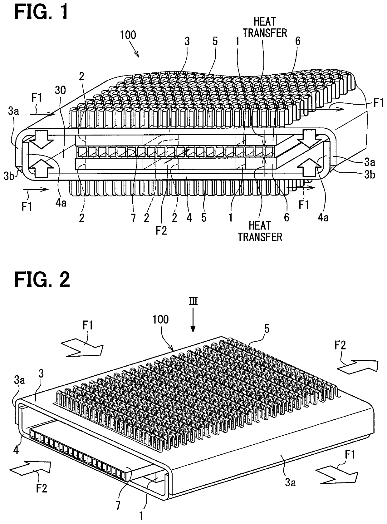
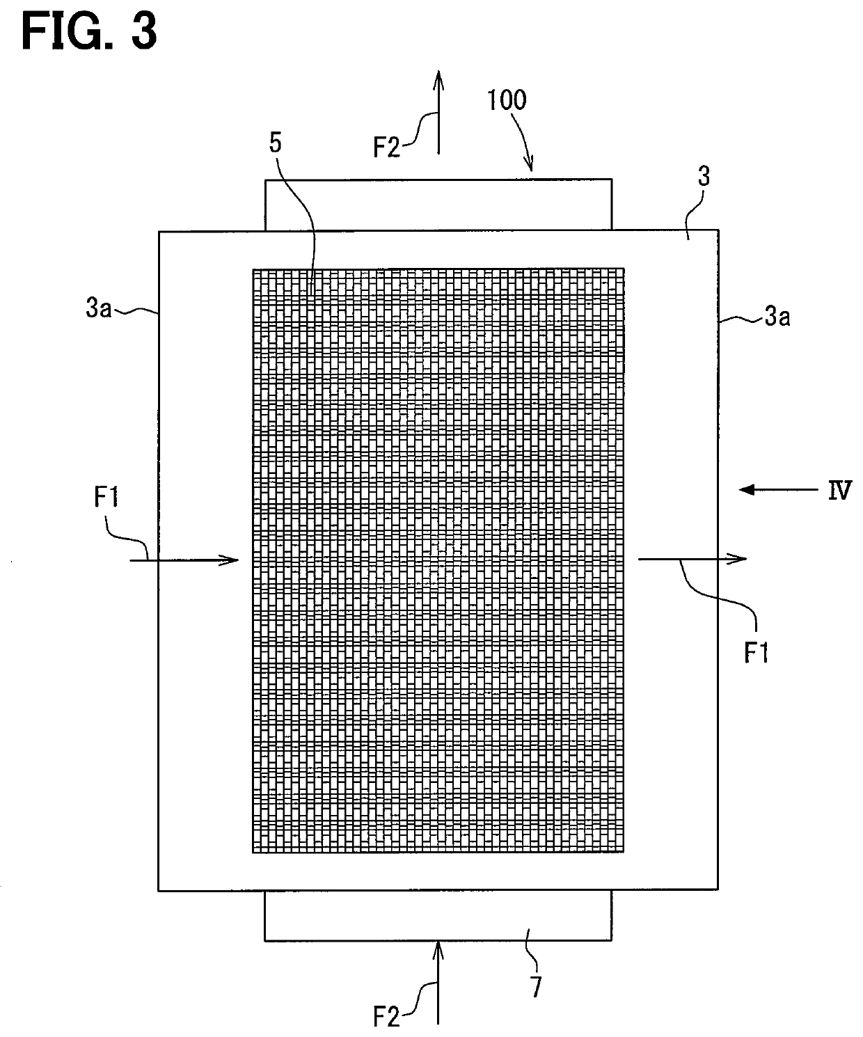
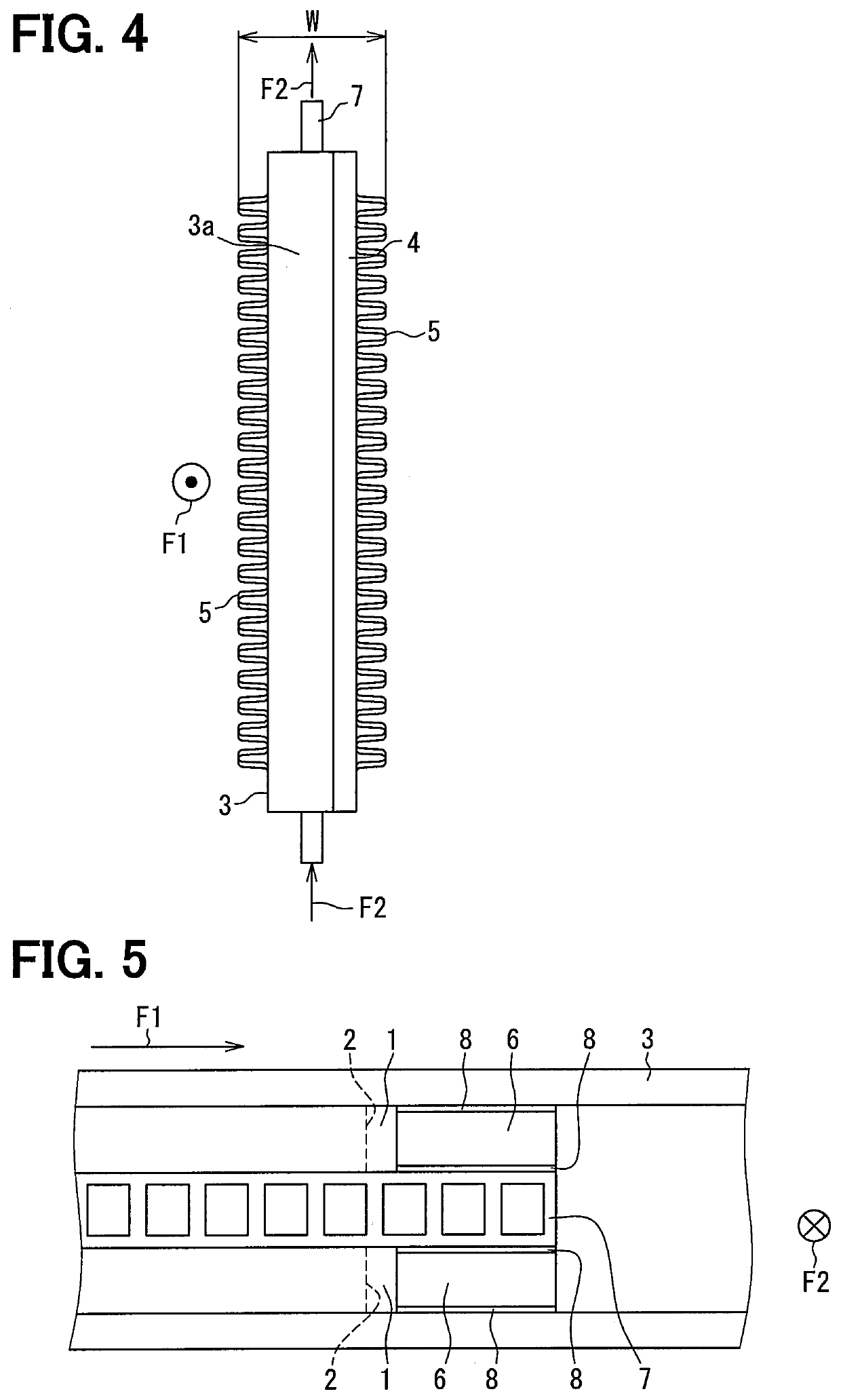
[0027]A thermoelectric power generator 100 of a first embodiment is described with reference to FIG. 1-FIG. 6. The thermoelectric power generator 100 is an equipment which can transform thermal energy into electric power energy by the Seebeck effect. When a difference in temperature is generated between one side and the other side in a power generation module having a thermoelectric conversion element, the thermoelectric power generator 100 generates electric power using phenomenon in which electrons flow due to potential difference. The difference in temperature is generated between the one side and the other side of the power generation module using a first fluid having low temperature and a second fluid having high temperature higher than the first fluid in the thermoelectric power generator 100. The first fluid and the second fluid are selected to provide the difference in temperature. In this embodiment, for example, the cooling water of an engine for a vehicle is used as the f...

second embodiment

[0062]A second embodiment is described with reference to FIG. 7. A configuration having the same reference numeral as the first embodiment in FIG. 7 is the same as that of the first embodiment. The configuration, processing, action, and effect not particularly explained in the second embodiment are the same as the first embodiment. Hereafter, only points different from the first embodiment are explained.

[0063]A thermoelectric power generator 200 of the second embodiment is different from the thermoelectric power generator 100 of the first embodiment in that a heat conductive component 106 is disposed between the power generation module 1 and the power generation module 1. The heat conductive component 106 has the same configuration and is made of the same material as the heat conductive component 6 to generate the same action and effect.

[0064]The thermoelectric power generator 200 includes the heat conductive component 106 which has thermal conductivity. The heat conductive componen...

third embodiment

[0068]A third embodiment is described with reference to FIG. 8. A configuration having the same reference numeral as the first embodiment in FIG. 8 is the same as that of the first embodiment. The configuration, processing, action, and effect not particularly explained in the third embodiment are the same as the first embodiment. Hereafter, only points different from the first embodiment are explained.

[0069]A pipe 107 of the third embodiment is different from the pipe 7 of the first embodiment in that the heat conductive component 6 is integrally formed with the pipe 107. The pipe 107 integrally includes the heat conductive component 6 projected from the respective sides of the pipe 107 at the downstream end in the flowing direction F1. The heat conductive component 6 in the pipe 107 is located downstream of the power generation module 1 in the flow of high-temperature fluid in the state where the power generation module 1 is in the tight contact with the respective sides of the pip...


PUM


Abstract

A thermoelectric power generator includes: a pipe in which a first fluid flows; a power generation module including a thermoelectric conversion element; and a holding member that is in contact with a one side part of the power generation module, such that heat of a second fluid that is higher in temperature than the first fluid transfers to the one side part of the power generation module. The holding member holds the power generation module and the pipe in a heat transferable state, such that the pipe is in contact with the other side part of the power generation module. The thermoelectric power generator includes a heat conductive component interposed between the holding member and the pipe to define a heat transfer course through which heat transfers from the second fluid to the first fluid, at downstream of the power generation module in a flowing direction of the second fluid.

Description

CROSS REFERENCE TO RELATED APPLICATION[0001]This application is based on Japanese Patent Application No. 2016-10071 filed on Jan. 21, 2016, and Japanese Patent Application No. 2016-232202 filed on Nov. 30, 2016, the disclosures of which are incorporated herein by reference.TECHNICAL FIELD[0002]The present disclosure relates to a thermoelectric power generator which transforms thermal energy into electric power energy by the Seebeck effect.BACKGROUND ART[0003]In a thermoelectric power generator, a power generation performance is determined based on a multiplication value of a heat recovery amount and a power generation efficiency. Further, the heat recovery amount and the power generation efficiency are in a relation of a trade-off. In order to get high power generation performance, it is necessary to increase the multiplication value of the heat recover amount and the power generation efficiency. The heat recover amount, at this time, falls compared with a heat recovery equipment wi...

Claims


Application Information

Patent Timeline
Patent Type & Authority Applications(United States)
IPC IPC(8): H01L35/32H01L35/30F01N5/02
CPCH01L35/32F01N5/025H01L35/30F01N3/0205F01N2240/02F01N2240/04F01N2260/10F01N2510/00F01N2530/04Y02T10/12H10N10/13H10N10/17
Inventor KITAGAWA, SHINYAOKAMOTO, YOSHIYUKIMATSUDA, TAKUYA
Owner DENSO CORP
Why Eureka
Try Eureka