Dental apparatus for shaping and cleaning a root canal

a technology for root canals and dental apparatuses, applied in the field of dental root canal work, to achieve the effect of assessing cutting efficiency and easy chang

Inactive Publication Date: 2009-05-28
MICRO MEGA INT MFG SA
View PDF4 Cites 11 Cited by
  • Summary
  • Abstract
  • Description
  • Claims
  • Application Information

AI Technical Summary

Benefits of technology

[0019]In particular for faster rotating files (up to 2000 rpm), it may only be necessary to generate a substantial reduction in speed of rotation to achieve the effect of the invention, although it may require a reverse current to achieve sufficient deceleration.
[0020]The motor is preferably a stepper motor which can be easily caused to change speed and / or direction, but the invention can also be used with a continuously rotating motor, particularly if the frequency and extent of the intermittent interruptions in the normal motor rotation can be established and programmed into the motor drive circuit.
[0021]The invention also extends to a method of shaping and cleaning a root canal using a dental drill driven by an electric motor, wherein an endodontic file is mounted in the drill head, the motor is operated at a normal speed in a normal rotational direction in which flutes of the file are in a cutting mode and while the file is within the root canal the motor is driven intermittently at a speed and / or direction substantially different from the normal speed or direction for a very short time.
[0022]Preferably, the speed substantially different from the normal speed is a speed in the opposite direction of rotation; i.e., the motor is intermittently rotated in a reverse direction compared to the normal speed direction.
[0023]The invention is not restricted to root canal dental work (it is possible that it could be used in post space preparation) or even to dental work in general. The method of the invention may be applied to any operation where it is desired to impart a pulse or vibration to a rotating bit (e.g. a drill or a file) while the bit is working, without stopping the bit from rotating and cutting.
[0024]It is widely accepted that a significant proportion of the loading on a rotary endodontic file is associated with the dentine debris created by the cutting process, both the friction component and also the management / discharging component.

Problems solved by technology

This play may be the result of backlash in a gear train, or any other type of play, or energy absorbtion between the motor and the endodontic file.

Method used


Image

  • Dental apparatus for shaping and cleaning a root canal
  • Dental apparatus for shaping and cleaning a root canal
  • Dental apparatus for shaping and cleaning a root canal

Examples


Embodiment Construction

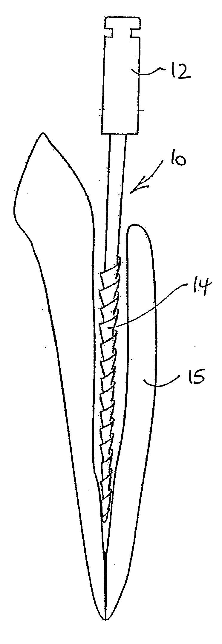
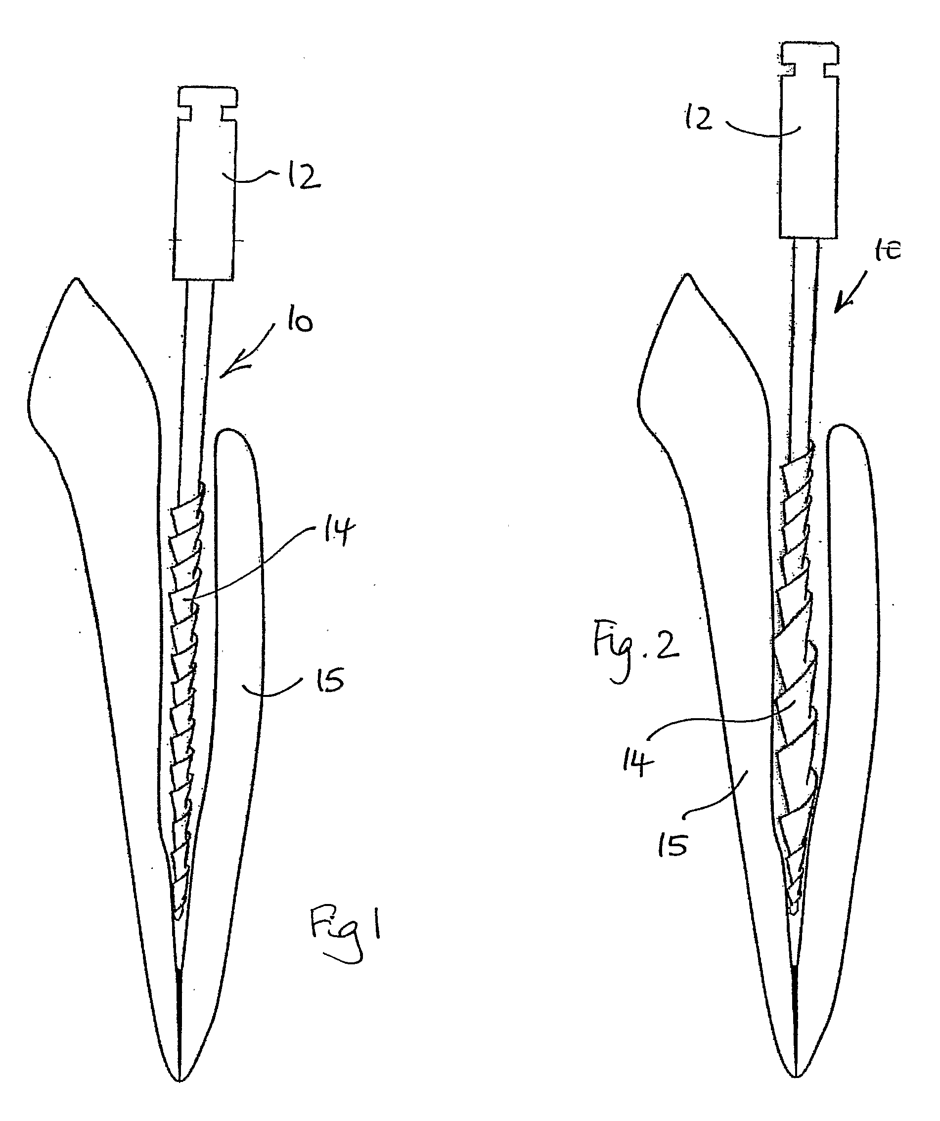
[0032]The endodontic file 10 shown in FIG. 1 has a mandrel 12 which is shaped to fit into the drill head of a drill handpiece, and a tapered, helically fluted working portion 14.

[0033]The file is designed to be rotated in one direction, and the flutes have a leading edge which cuts or scrapes the dentine from the walls of the tooth's root canal. As the files rotate, they cut dentine from the walls of the tooth and also collect the remaining soft pulp tissue.

[0034]The file is made of a flexible metal alloy, so that it can bend, whilst still being rotated, to follow the curves of a root canal, which may follow a meandering path. The flexibility of the alloy also means that the file will “wind up”; i.e., the file will be twisted, when torque is applied to the head of the file and when part of the file is in frictional contact with the root canal walls. This winding up of the file will result in a radial expansion of the part of the file between the part in frictional contact with the r...


PUM


Abstract

Apparatus is disclosed for use in cleaning dental root canals using an endodontic file. The file is mounted in a drill head driven by an electric motor. The motor is normally driven in one, forward direction, but periodically, the motor rotation is reversed for a very short time. The duration of the motor reversal is so short that although the motor rotates in the reverse direction, the inertia and backlash in the transmission between the motor output shaft and the drill head is such that the direction of rotation of the file in the root canal is not changed.

Description

CROSS-REFERENCE TO RELATED U.S. APPLICATIONS[0001]Not applicable.STATEMENT REGARDING FEDERALLY SPONSORED RESEARCH OR DEVELOPMENT[0002]Not applicable.NAMES OF PARTIES TO A JOINT RESEARCH AGREEMENT[0003]Not applicable.REFERENCE TO AN APPENDIX SUBMITTED ON COMPACT DISC[0004]Not applicable.BACKGROUND OF THE INVENTION[0005]1. Field of the Invention[0006]This invention relates to dental root canal work, and in particular to an apparatus for shaping and cleaning a root canal in preparation for filling that canal.[0007]2. Description of Related Art Including Information Disclosed Under 37 CFR 1.97 and 37 CFR 1.98.[0008]Endodontics is the name given to root canal treatment. Endodontic treatment conventionally involves removal of the irreversibly damaged nerve tissue or pulp and some dentine, followed by cleaning and disinfection of the root canal space and subsequent obturation or filling of the canal to form a seal capable of preventing future bacterial penetration.[0009]Shaping and cleanin...

Claims


Application Information

Patent Timeline
Patent Type & Authority Applications(United States)
IPC IPC(8): A61C5/02A61C5/40
CPCA61C1/003A61C1/12A61C1/06A61C5/02A61C5/40A61C1/00
Inventor MEYER SHUSTER, DAVID
Owner MICRO MEGA INT MFG SA
Why Eureka
Try Eureka