Multilayer Interventional Catheter

a multi-layer, catheter technology, applied in the direction of balloon catheters, catheters, surgery, etc., can solve the problems of spiral wound guidewire capture risk, friction and clogging problem, still existent, etc., to improve the manufacture, reduce the friction coefficient, and improve the effect of quality

Inactive Publication Date: 2009-05-28
BOSTON SCI CORP
View PDF99 Cites 5 Cited by
  • Summary
  • Abstract
  • Description
  • Claims
  • Application Information

AI Technical Summary

Benefits of technology

[0010]Accordingly, where the catheter comprises mediator layer means arranged between the inner layer and the outer layer for the adhesive anchorage of the layers thereto, securing of the inner layer and outer layer is strongly enhanced independently of their intrinsic capacity of adhesion to one another. The risk of a poor adhesion or the risk of a failure in the adhesion of the two layers to one another is eliminated. The inner and outer layers may be chosen for their most appropriate mechanical characteristics rather than for their capacity to adhere to one another. Because of the adhesive anchorage of the inner and outer layers on the mediator layer means, the risk of separation of the two layers upon insertion of the catheter tube over a guidewire is minimized. And the assembly of inner and outer layers is under control and the possibilities of changing the flexibility of the assembly are improved; due to the adhesive anchorage on the mediator layer means, rigidity of the assembly is enhanced with the same basic inner and outer layers, whereas flexibility of the assembly may be mastered by safely acting on the thickness of the inner and outer layers, with the resulting reduction in the profile of the catheter. As a result of the adhesive anchorage of the inner and outer layers on the mediator layer means the assembly behaves like a unit; accordingly, the assembly may be safely grabbed by the outer layer and tear tests are thus facilitated.
[0011]The inner and outer layers and the mediator layer means may be congruent in length, so that the catheter shaft can be produced in long tubes which may be cut at will to the appropriate length. Where the inner layer, the mediator layer means and the outer layer are coextruded, a catheter tube is formed in a continuous process avoiding the need of using a core in the inner layer.
[0012]Where the inner and outer layers are substantially transparent and the mediator layer means are contrasted with respect to the substantially transparent inner and outer layers, a visual control of the assembly is readily available to further improve the manufacture.
[0014]When the inner layer is formed of a material with lower friction coefficient than the material forming the outer layer, there is no more risk of having the guidewire clogging or being captured in the guidewire lumen of the catheter tube. Withdrawal and re-positioning of the balloon catheter on a guidewire left in place at the site of treatment in the vessel system is rapid, safe and precise. Furthermore, the choice can be made for materials for the inner and outer layers having the most appropriate friction and kink resistance coefficients, while safe attachment of the balloon may be made at will on the outer layer which is chosen without being influenced by the friction properties of the inner layer.
[0015]The mediator layer means may be formed on the basis of a low density polyethylene to offer superior adhesion performance in a wide variety of configurations of the inner and outer layers and ease of processing on conventional fabrication equipment.
[0016]In a preferred form of the invention, the inner layer is made of a polyethylene or of a high density polyethylene, both of which assure an extremely low friction coefficient and an appropriate kink resistance coefficient. In another preferred form of the invention, the outer layer is made of a polyamid to assure easy welding of the balloon and a good stiffness at that level.

Problems solved by technology

A problem with these catheters is that the guidewire may clog into the guidewire lumen of the catheter, whereby the guidewire may follow the balloon upon withdrawal thereof after the inflation procedure thereby making it necessary to re-insert the guidewire into the treated area of the blood vessel for repositioning a balloon therein in case a second inflation is needed.
A further problem is that the catheter has to achieve an acceptable compromise between the requirements of some stiffness to assure good pushability and some flexibility to assure kink resistance.
Though limited, the friction and clogging problem is, however, still existent.
There would be therefore the risk that a spiral wound guidewire could be captured in the soft elastomeric plastic material of the inner layer of the elongated member.
Although the outer layer of the elongated member that is coextruded onto the inner layer is formed of nylon, a material which is expected to be directly weldable to a wide variety of materials, this balloon apparatus cannot be introduced into narrow vessels or narrow stenoses, nor can it be passed through narrow punctures to enter the blood vessels.
In terms of two layers catheter shafts, it has been observed that in practical use the adhesion of the two layers of material was not absolutely satisfactory.
Furthermore, tear test effected on such structures has shown that the two layers can separate under extreme conditions of stress on the shaft.

Method used


Image

  • Multilayer Interventional Catheter
  • Multilayer Interventional Catheter
  • Multilayer Interventional Catheter

Examples


Embodiment Construction

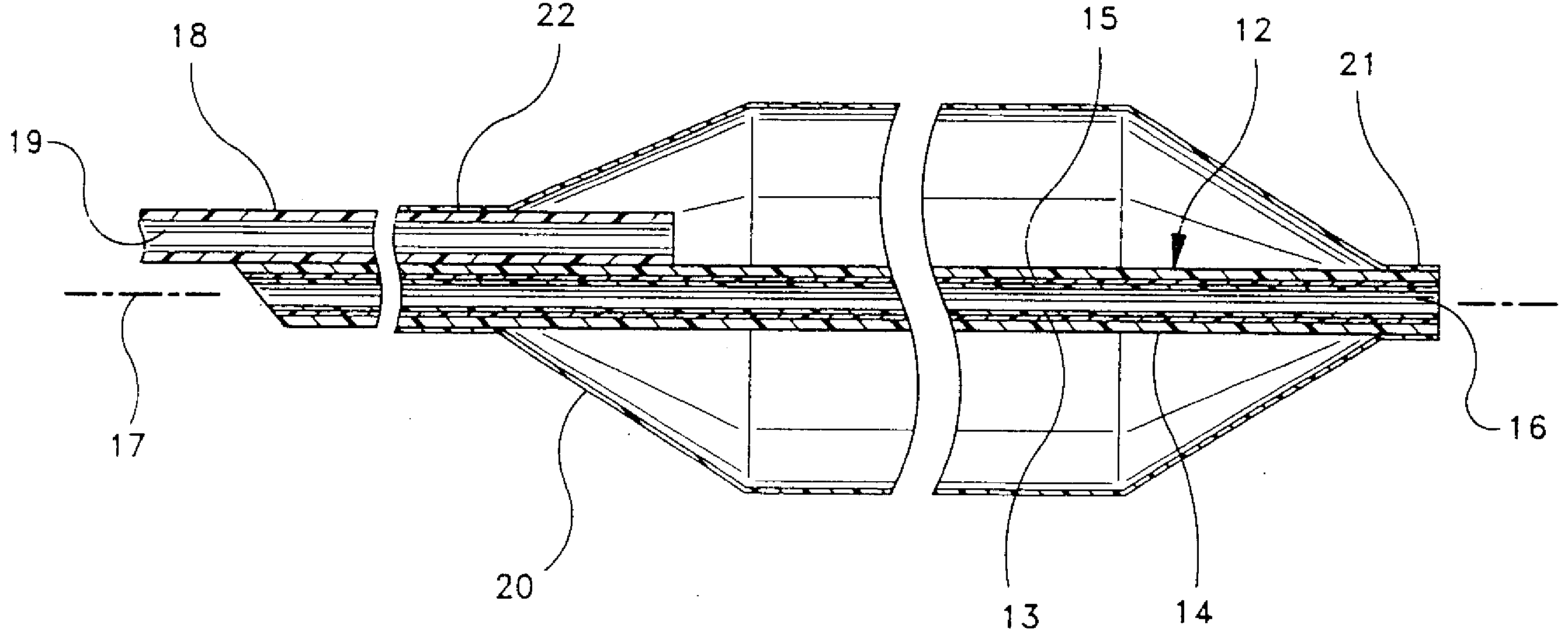
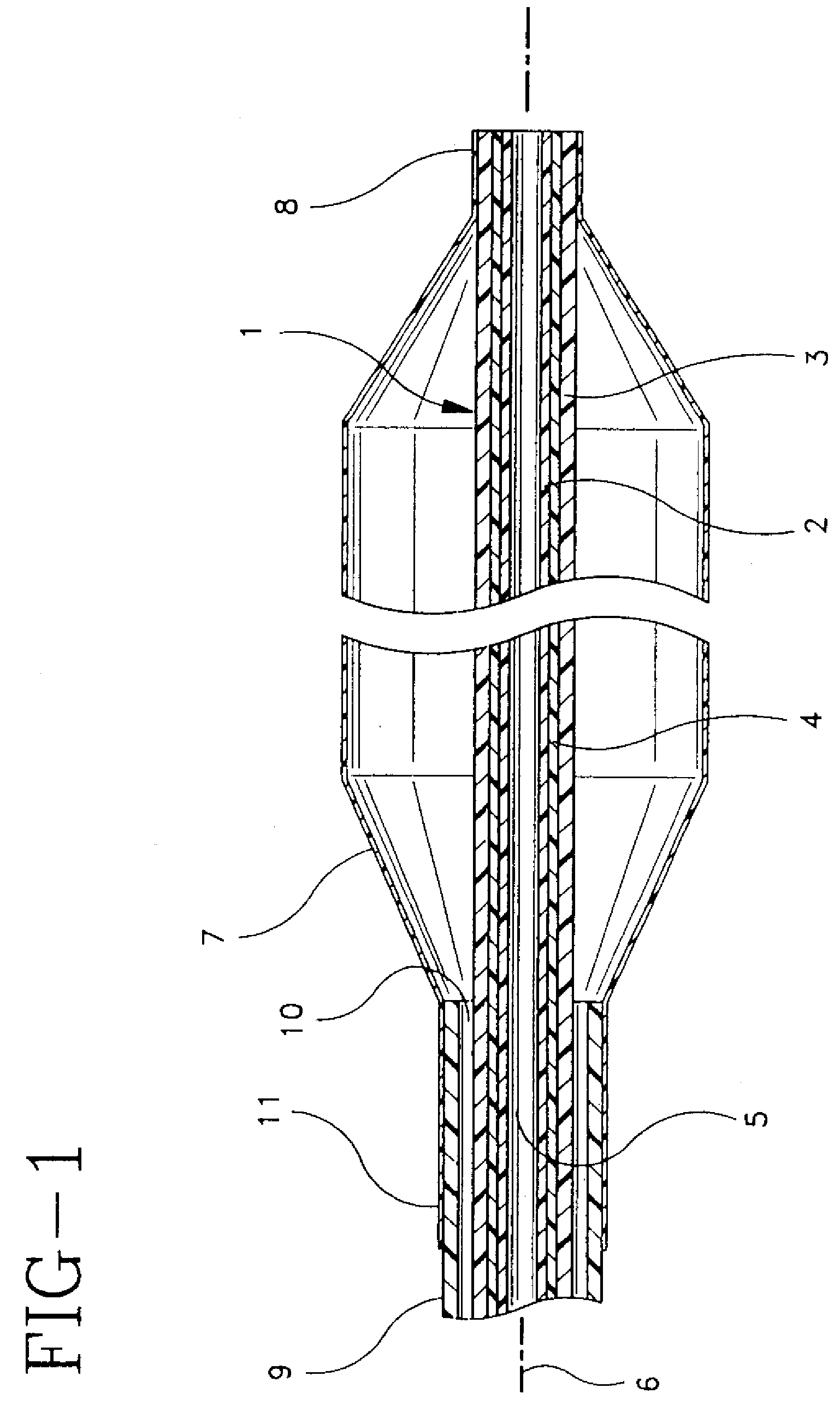
[0023]The interventional catheter shown in FIG. 1 comprises a catheter tube 1 formed of two superposed tubular layers of materials 2 and 3 with a tubular mediator layer 4 arranged therebetween for the adhesive anchorage of the layers 2 and 3 onto the mediator layer 4.

[0024]The tubular layers 2, 3, and 4 extend all over the length of catheter tube 1, being thus congruent in length, and the assembly of layers forming the catheter tube 1 may be obtained by the known coextrusion technology, i.e., by extruding simultaneously the inner layer 2 with the mediator layer 4 and with the outer layer 3 thereover. Layers 2 and 3 have mechanical properties differing from one another and, preferably, mediator layer 4 also has mechanical properties differing from the mechanical properties of inner and outer layers 2 and 3.

[0025]Preferably, the inner layer 2 is formed of a material with lower friction coefficient than the material forming the outer layer 3. For example, the inner layer 2 may be forme...


PUM

PropertyMeasurementUnit
friction coefficientaaaaaaaaaa
mechanical propertiesaaaaaaaaaa
lengthaaaaaaaaaa

Abstract

The catheter comprises a catheter tube formed of two superposed tubular layers of materials which differ from one another. A tubular mediator layer is arranged between the layers to provide an adhesive anchorage for the layers.

Description

CROSS-REFERENCE TO RELATED APPLICATIONS[0001]This application is a continuation of pending U.S. application Ser. No. 10 / 697,613, filed Oct. 29, 2003; which is a continuation of U.S. application Ser. No. 09 / 978,964, filed Oct.15, 2001, now U.S. Pat. No. 6,659,977; which is a continuation of U.S. application Ser. No. 08 / 845,569, filed Apr. 25, 1997, now U.S. Pat. No. 6,319,228; which claims priority to European Application No. 96106578.6, filed Apr. 26, 1996, the entire disclosures of which are all incorporated herein by reference.BACKGROUND OF THE INVENTION[0002]This invention relates to an interventional catheter comprising a catheter tube having two superposed layers of materials secured together and with mechanical properties differing from one another, a guidewire lumen in the catheter tube for the sliding fit of a guidewire, and a balloon with a distal end sealingly surrounding the catheter tube whereby the catheter tube has an inner layer forming the guidewire lumen and an oute...

Claims


Application Information

Patent Timeline
Patent Type & Authority Applications(United States)
IPC IPC(8): A61M25/10A61M25/00A61F2/958A61M29/02
CPCA61M25/00A61M25/0045A61M25/10A61M25/1027A61M2025/0183A61M25/1036A61M25/104A61M29/02A61M2025/0047A61M25/1034
Inventor KASTENHOFER, GERHARD
Owner BOSTON SCI CORP
Why Eureka
Try Eureka