Motion-resolving hover display

a technology of hover display and motion resolution, applied in the field of flight instruments, can solve the problems of difficult learning of hovering, failure to master the art of hovering and maneuvering at low speed, and instruments that do not provide an integrated and readily perceived picture of the motion of the aircra

Active Publication Date: 2009-05-28
FLORIDA INST FOR HUMAN & MACHINE COGNITION
View PDF38 Cites 47 Cited by
  • Summary
  • Abstract
  • Description
  • Claims
  • Application Information

AI Technical Summary

Benefits of technology

[0020]The present invention is an integrated flight instrument which provides clear information regarding the attitude and motion of a hovering aircraft. The instrument accurately depicts motion in six degrees of freedom (roll, pitch, yaw, forward / rearward translation, lateral translation, and vertical translation). It also provides information about the aircraft's power requirements and settings.

Problems solved by technology

It is also true that an airspeed indicator provides forward speed and a vertical speed indicator provides information regarding upward and downward motion, but these instruments do not provide an integrated and readily perceived picture of the aircraft's motion, especially the slower motion occurring while hovering.
Hovering is a very difficult task to learn.
The result is that many students who are capable of learning to fly a helicopter in the aerodynamic flight regime (flight above approximately 30 mph) fail to master the art of hovering and maneuvering at low speeds.
When this initially proved unsuccessful, the suspected problem was a lack of visual resolution in the simulation.
However, as more and more detailed simulations evolved, the problem persisted.
However, understanding what the observation means in terms of the motion of the helicopter is much more difficult.
However, as for the case of looking out the nose of the helicopter, these lateral visual cues are ambiguous.
Resolving the ambiguity is an exceedingly complex task.
Similar visual ambiguities occur when making observations out the left side of the helicopter, and when trying to discern rearward motion.
There is no clearly defined method for teaching these skills.
Of course, some student pilots are ultimately unable to master this skill.
These instruments are certainly useful, but they do not resolve the motion ambiguities present during hover maneuvers.
In a hover maneuver, there is rarely enough time to perform such a scan and mental integration.
In addition, even if the scan and mental integration step could be performed rapidly enough, existing flight instruments simply do not provide enough information for hovering maneuvers.

Method used


Image

  • Motion-resolving hover display
  • Motion-resolving hover display
  • Motion-resolving hover display

Examples


Embodiment Construction

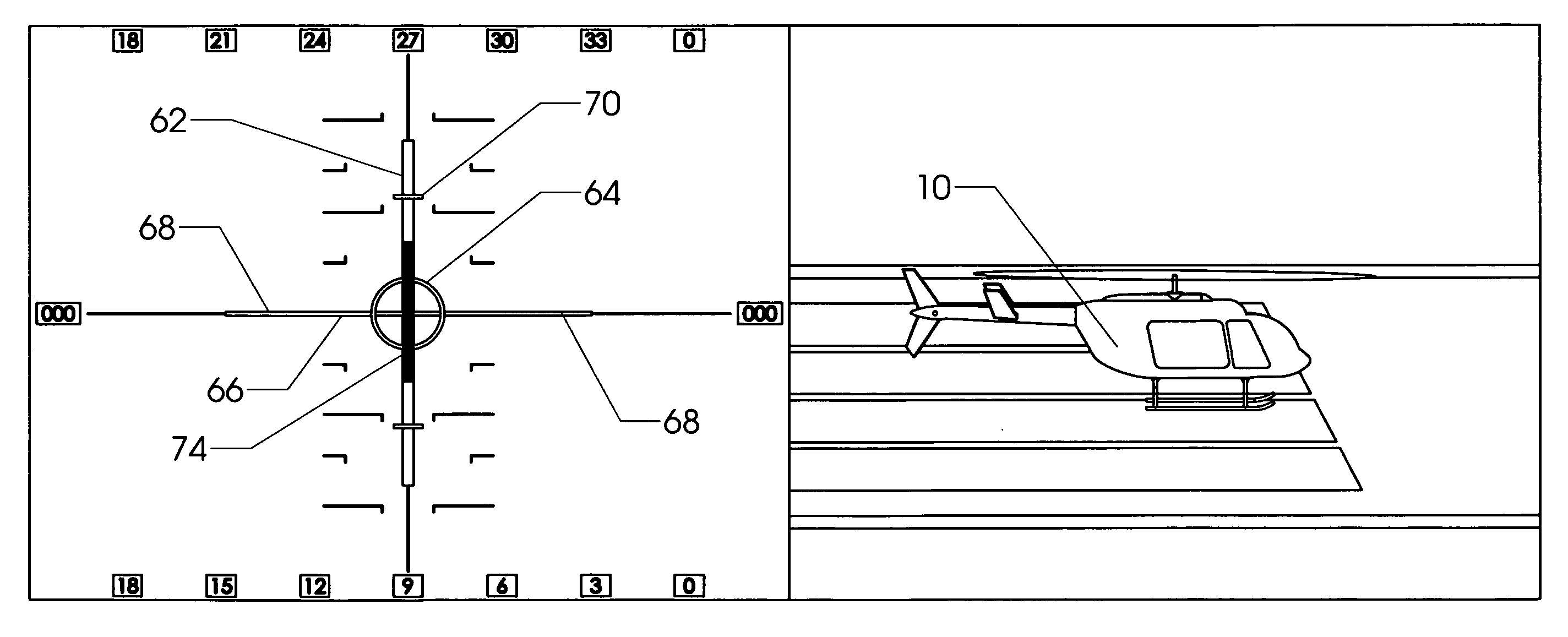
[0099]The present invention is a flight instrument designed to provide a wealth of information to a pilot flying an aircraft, particularly when the aircraft is performing hover maneuvers. The flight instrument will be referred to as a “hover display.” The hover display could be physically realized in many different ways. However, as the use of flat-panel electronic displays is now common in aviation, an embodiment using this approach will be described. Those skilled in the art will know that such flat panels can be constructed using LCD's, plasma displays, and the like. The physical construction of such components is well beyond the scope of this disclosure, and in any event well understood by those with knowledge of avionics.

[0100]FIG. 8 shows the first portion of the display, which will be referred to as the external reference display. It is conceptually similar to prior art attitude indicators, which are also sometimes known as “artificial horizons.” Horizon line 52 represents th...


PUM


Abstract

An integrated flight instrument which provides unambiguous information regarding the motion of a hovering aircraft. The instrument accurately depicts motion in six degrees of freedom (roll, pitch, yaw, forward translation, lateral translation, and vertical translation), as well as aircraft power requirements and utilization.

Description

STATEMENT REGARDING FEDERALLY SPONSORED RESEARCH OR DEVELOPMENT[0001]The invention disclosed herein has been funded at least in part by the federal government.CROSS-REFERENCES TO RELATED APPLICATIONS[0002]Not ApplicableMICROFICHE APPENDIX[0003]Not ApplicableBACKGROUND OF THE INVENTION[0004]1. Field of the Invention[0005]This invention relates to the field of aviation. More specifically, the invention comprises a flight instrument which clearly displays the attitude and motion of a hovering aircraft to its pilot.[0006]2. Description of the Related Art[0007]The present invention primarily applies to aircraft which are in low-speed or hovering flight. It is useful in conventional rotorwing aircraft such as helicopters and “unconventional” hovering aircraft such as the Bell / Boeing V-22 Osprey and the McDonald Douglass AV-8B Harrier II.[0008]Although the flight dynamics of a hovering aircraft will be familiar to those skilled in the art, a brief explanation of these dynamics may be helpf...

Claims


Application Information

Patent Timeline
Patent Type & Authority Applications(United States)
IPC IPC(8): G05D1/08
CPCG01C23/00
Inventor STILL, DAVID L.ESKRIDGE, THOMAS C.TEMME, LEONARD A.
Owner FLORIDA INST FOR HUMAN & MACHINE COGNITION
Why Eureka
Try Eureka