Method for setting parameters and determining latency in a chained device system

a chained device and parameter technology, applied in the field of memory components, can solve the problems of complex protocols, information processing latency, and traditional attempts at memory control that are often very convoluted and complex, and achieve the effect of reducing response time and maximising latency

Active Publication Date: 2009-05-28
SPANSION LLC +1
View PDF14 Cites 19 Cited by
  • Summary
  • Abstract
  • Description
  • Claims
  • Application Information

AI Technical Summary

Benefits of technology

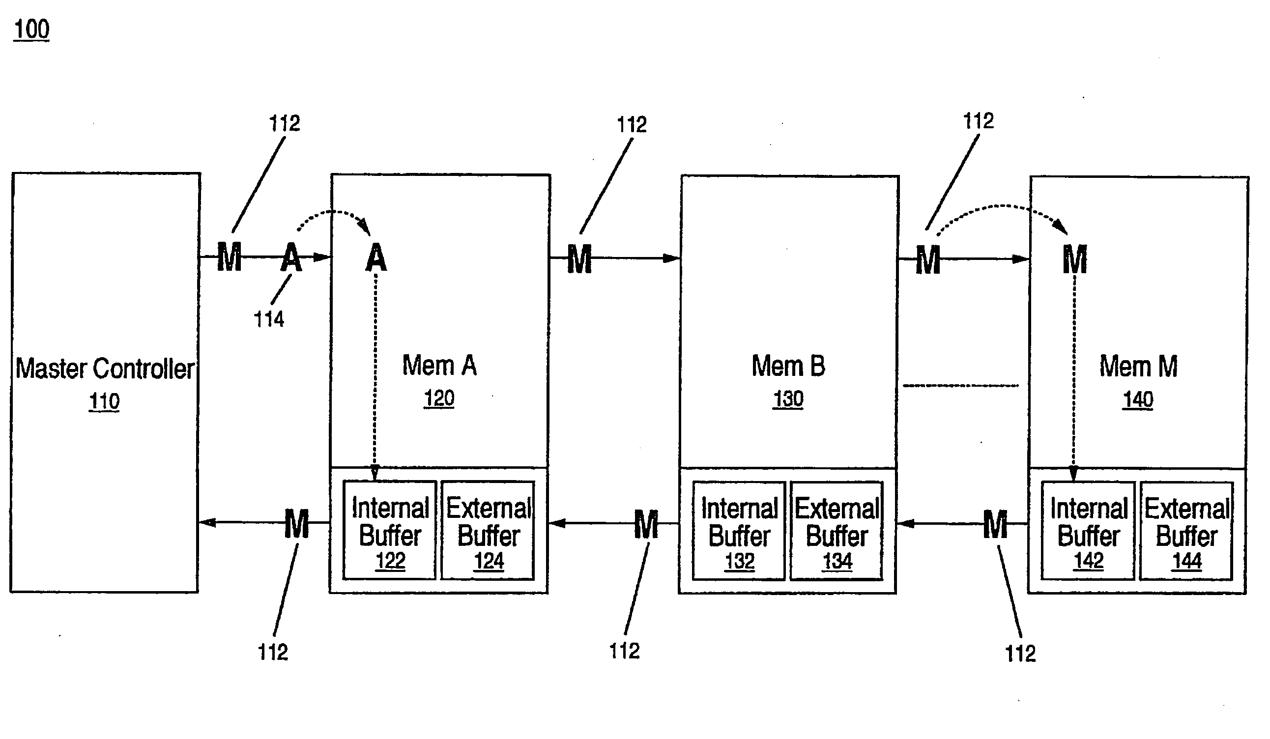
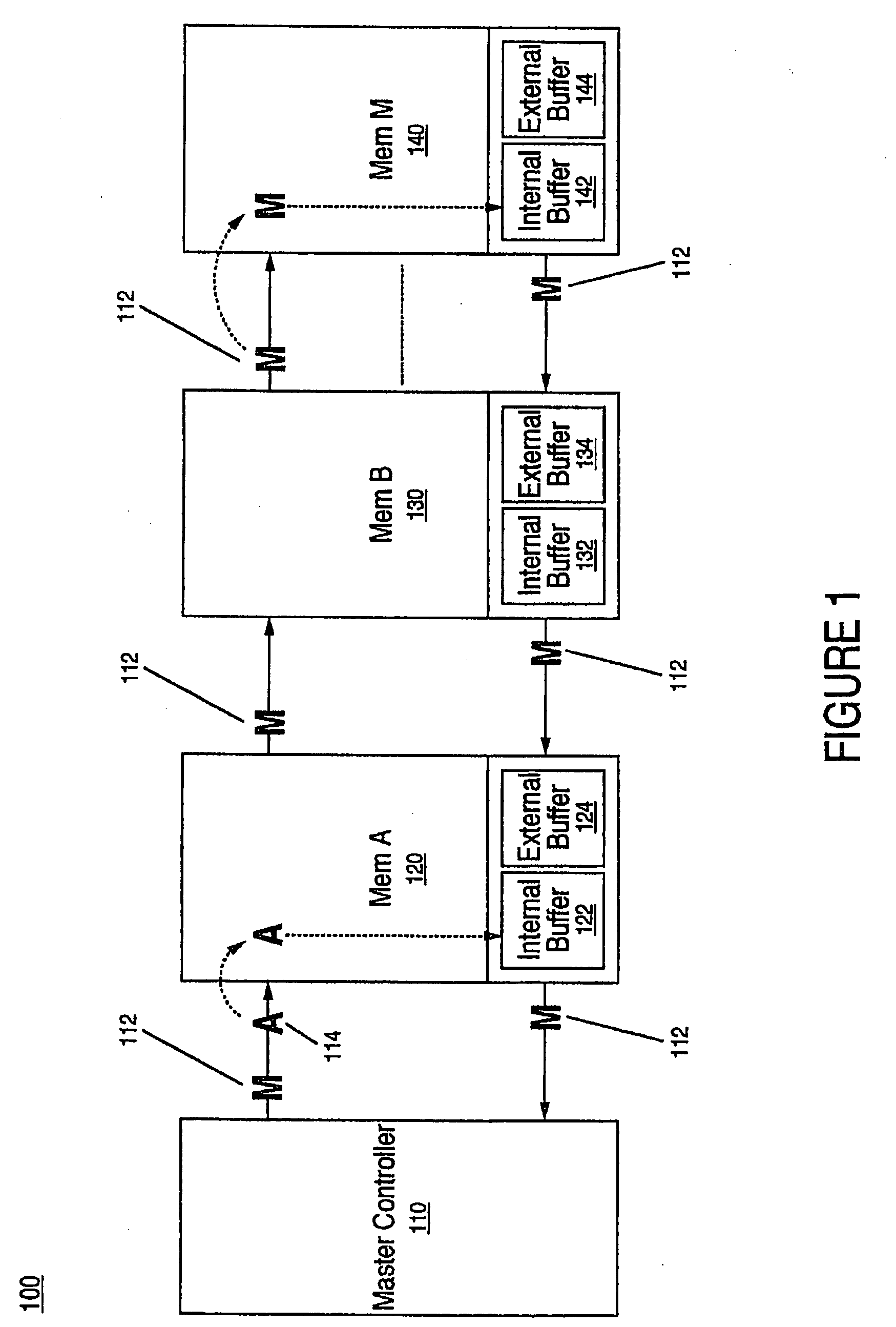
[0013]In one embodiment of the present invention, the master controller controls the flow of information to the storage nodes based on one or more constraints of the upstream communication buffer, e.g., internal and external buffers, of the storage nodes. The master controller controls the flow of information such that communication between the master controller and the storage nodes have a determined maximum latency. According to one embodiment, the constraint of the upstream communication buffer is based on providing priority to responses to a storage node, e.g., memory node, that are further down the daisy chain stream.
[0015]As a result, the maximum latency of any request, e.g., read request, may be defined using the same equation and the minimum latency of a given storage node in the system. Thus, the master controller, e.g., CPU, may build requests to be sent to storage nodes based on the apriori knowledge of latency for each node in order to reduce response time in the daisy chain system.

Problems solved by technology

However, accessing memory resources in a fast and efficient manner can involve complicated protocols.
The ability to access a memory and transfer information quickly and conveniently usually has a significant impact on information processing latency.
Traditional attempts at memory control are often very convoluted and complex.
Conventional daisy chain systems often involve latencies that can become very large due to large buffer sizes and scheduling amongst the various nodes within the daisy chain.
It is often problematic for controllers and / or central processors to determine latency for read requests without complex scheduling algorithms and artificial limitations of the system.
Traditional approaches often lead to long average latencies, very complex control mechanisms, larger buffer sizes, or a combination of such problematic concerns.

Method used


Image

  • Method for setting parameters and determining latency in a chained device system
  • Method for setting parameters and determining latency in a chained device system
  • Method for setting parameters and determining latency in a chained device system

Examples


Embodiment Construction

[0019]Reference will now be made in detail to embodiments of the present invention, examples of which are illustrated in the accompanying drawings. While the invention will be described in conjunction with these embodiments, it will be understood that they are not intended to limit the invention to these embodiments. On the contrary, the invention is intended to cover alternative, modifications and equivalents, which may be included within the spirit and scope of the invention as defined by the appended claims. Furthermore, in the following detailed description of the present invention, numerous specific details are set forth in order to provide a thorough understanding of the present invention. However, it will be evident to one ordinary skill in the art that the present invention may be practiced without these specific details. In other instances, well known methods, procedures, components, and circuits have not been described in detail as not to unnecessarily obscure aspects of t...


PUM


Abstract

A storage system and method for setting parameters and determining latency in a chained device system. Storage nodes store information and the storage nodes are organized in a daisy chained network. At least one of one of the storage nodes includes an upstream communication buffer. Flow of information to the storage nodes is based upon constraints of the communication buffer within the storage nodes. In one embodiment, communication between the master controller and the plurality storage nodes has a determined maximum latency.

Description

RELATED APPLICATIONS[0001]This application claims the benefit and priority to a provisional application Ser. No. 61 / 004,412 with attorney docket No. SPSN-AF02875.PRO, inventors Miura et al., entitled “A METHOD FOR SETTING PARAMETERS AND DETERMINING LATENCY IN A CHAINED DEVICE SYSTEM” that was filed on Nov. 26, 2007 and is hereby incorporated by reference in its entirety.[0002]Moreover, this application claims priority to and the benefit of the provisional patent application, Ser. No. 61 / 004,362, Attorney Docket Number SPSN-AF02874.Pro, inventors Miura et al., entitled “A SYSTEM AND METHOD FOR ACCESSING MEMORY,” with filing date Nov. 26, 2007, and hereby incorporated by reference in its entirety.[0003]Furthermore, this application claims the benefit of and priority to co-pending provisional application Ser. No. 61 / 004,434 with attorney docket number SPSN-AF02873.PRO, inventors Miura et al., entitled “A STORAGE SYSTEM AND METHOD” that was filed on Nov. 26, 2007 and is hereby incorpora...

Claims


Application Information

Patent Timeline
Patent Type & Authority Applications(United States)
IPC IPC(8): G06F15/16
CPCG06F13/1684G06F13/1673
Inventor MIURA, SEIJIISAAC, ROGER DWAIN
Owner SPANSION LLC
Why Eureka
Try Eureka