

Apparatus and Methods for Continuous Tomography of Cores
a technology of tomography and apparatus, applied in the field of apparatus and methods for tomography of cores, can solve the problems of not being conducive to continuous coring (coring beyond the core barrel length) or to taking measurements
- Summary
- Abstract
- Description
- Claims
- Application Information
AI Technical Summary
Benefits of technology
Problems solved by technology
Method used
Image

Examples
Embodiment Construction
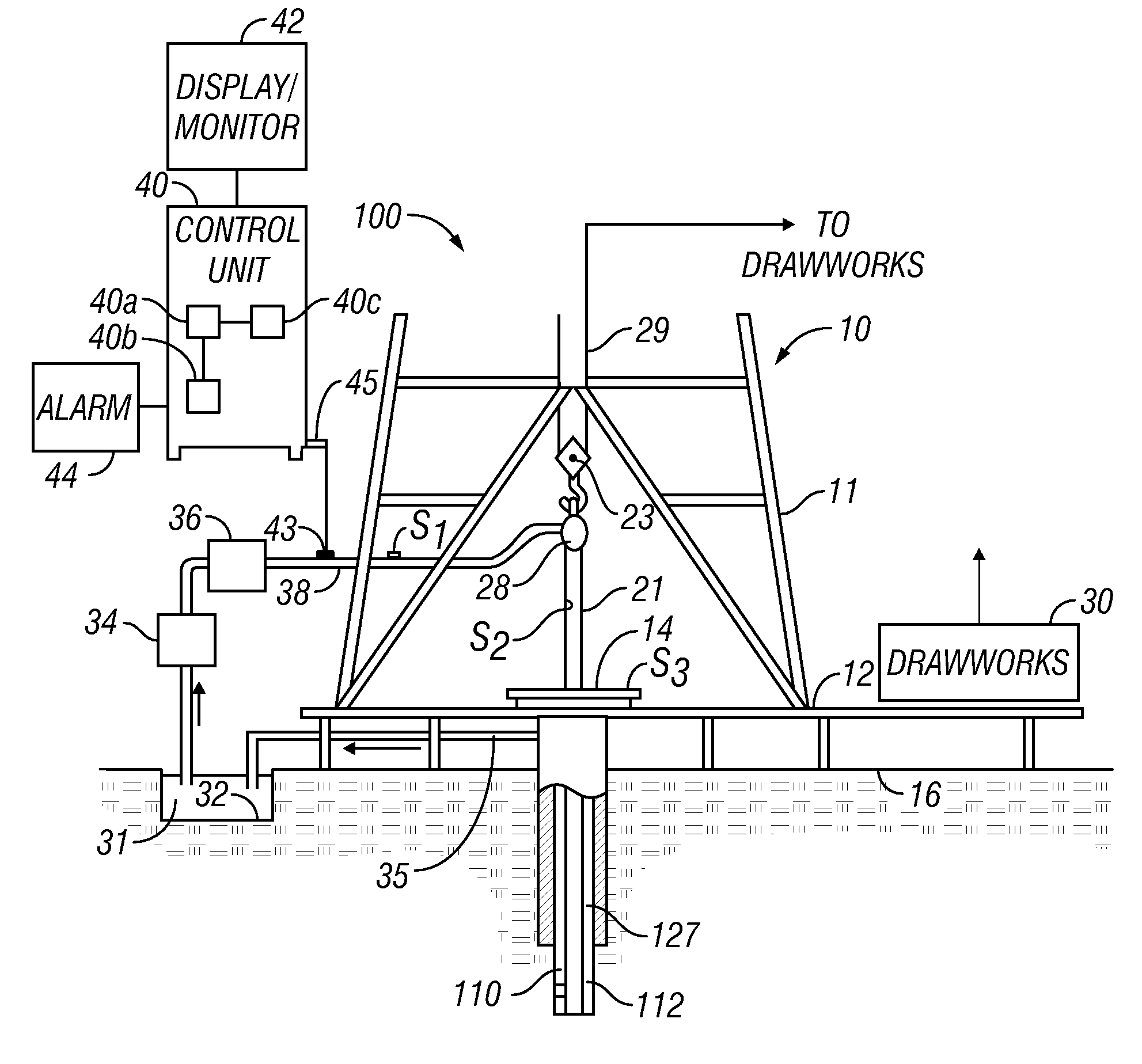
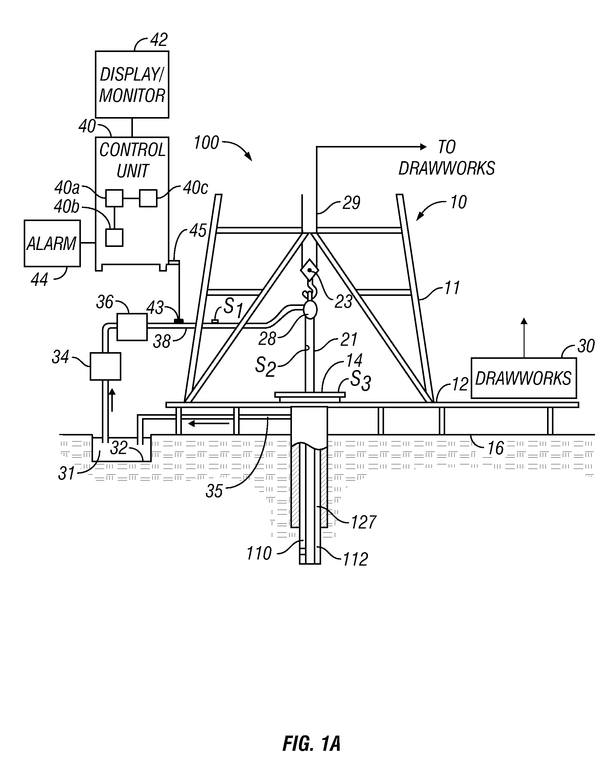
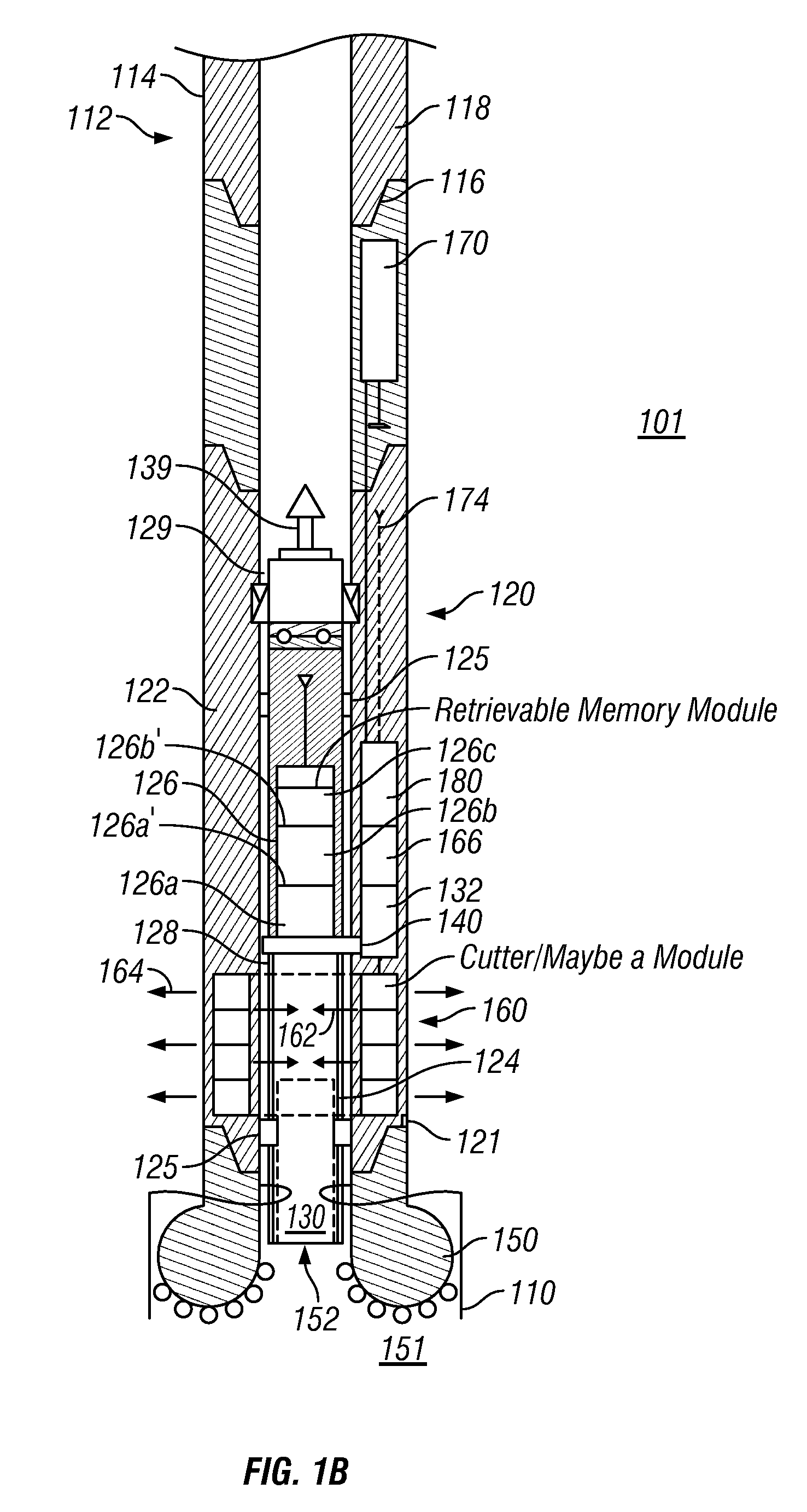
[0023]FIG. 1 (comprising FIG. 1A and FIG. 1B) is a schematic diagram showing an exemplary drilling system 100 that may be utilized for continuous coring, selectively storing core samples, estimating one or more properties of the core and / or estimating formation parameters during drilling of a wellbore 110 according to one aspect of the disclosure. FIG. 1 shows a wellbore 110 being drilled with a drill string 112 in a formation 101. The drill string 112, in one aspect, includes a tubular member 114 and a drilling assembly 120, also referred to as a “bottomhole assembly” or “BHA” attached at its bottom end 118 with a suitable connection joint 116. The tubular member 114 is typically made up by connecting drill pipe sections. A drill bit 150 (also referred to herein as the “coring bit”) is attached to the bottom end 121 of the drilling assembly 120 for drilling the wellbore 110 in the formation 101. The drill bit 150 has a through bore or mouth 152 having a diameter substantially equal...
PUM
 Abstract
Description
Claims
Application Information