System for deployment of a millimeter wave concealed object detection system using an outdoor passively illuminated structure

a concealed object and passive illumination technology, applied in the field of deployment systems, can solve the problems of exposing not only security personnel to danger, but also other individuals in the vicinity, concealing objects that present dangers, and reducing so as to simplify the repair or replacement of a damaged deployment, reduce the risk of the parent structure, and simplify training and use. the effect of ease of us

Inactive Publication Date: 2009-06-04
MICROSEMI
View PDF7 Cites 4 Cited by
  • Summary
  • Abstract
  • Description
  • Claims
  • Application Information

AI Technical Summary

Benefits of technology

[0016]One particular advantage provided by embodiments of the system for deployment of a millimeter wave concealed object detection system using an outdoor passively illuminated structure is that the components, techniques, designs and construction separately, or in combination, provide an advantageous, predictable, controlled and managed environment within which the concealed object detection system operates optimally. Another advantage provided by embodiments of the system is that the need to adapt the system's cameras to an uncontrolled environment is eliminated and the system can eliminate the need to custom engineer a deployment for each application. In addition, the system can simplify training and ease of use owing to the fact that each deployment is the same as (or very similar to) another. This would not be the case for a customized / unique deployment for each concealed object detection installation.
[0017]Another particular advantage provided by embodiments of the system for deployment of a millimeter wave concealed object detection system using an outdoor passively illuminated structure is that the system eliminates the need for the parent structure or area to be modified, expanded or re-engineered in order to accommodate the concealed object detection system equipment and logistics.
[0018]Another advantage provided by embodiments of the system is that the system can reduce the risk to the parent structure by containing the threat detection process and perhaps explosive blasts within an external building designed with blast mitigation techniques. The system can simplify the repair or replacement of a damaged deployment should it become necessary (e.g., due to an explosives detonation). The system can provide a stable, standard platform for deployments across extremely variable environments, resulting in lower installation costs and time, and simpler construction and support due to the standardized methodology. Further, the system allows for a realization of manufacturing, engineering and procurement cost savings due to economies of scale.

Problems solved by technology

The concealed objects that present a danger are weapons, explosives, contraband and other similar items that may endanger security personnel and other individuals in the proximity.
An inherent deficiency of this type of security system is the fact that it exposes not only the security personnel to danger, but also other individuals in the vicinity of the security system to the dangers posed by such concealed objects.
However, there is still a concern that when a concealed object is detected on a person, that the person may attempt to escape the area or injure others in the proximity using an explosive device (i.e., suicide bomber).
The system can provide a stable, standard platform for deployments across extremely variable environments, resulting in lower installation costs and time, and simpler construction and support due to the standardized methodology.

Method used


Image

  • System for deployment of a millimeter wave concealed object detection system using an outdoor passively illuminated structure
  • System for deployment of a millimeter wave concealed object detection system using an outdoor passively illuminated structure
  • System for deployment of a millimeter wave concealed object detection system using an outdoor passively illuminated structure

Examples


Embodiment Construction

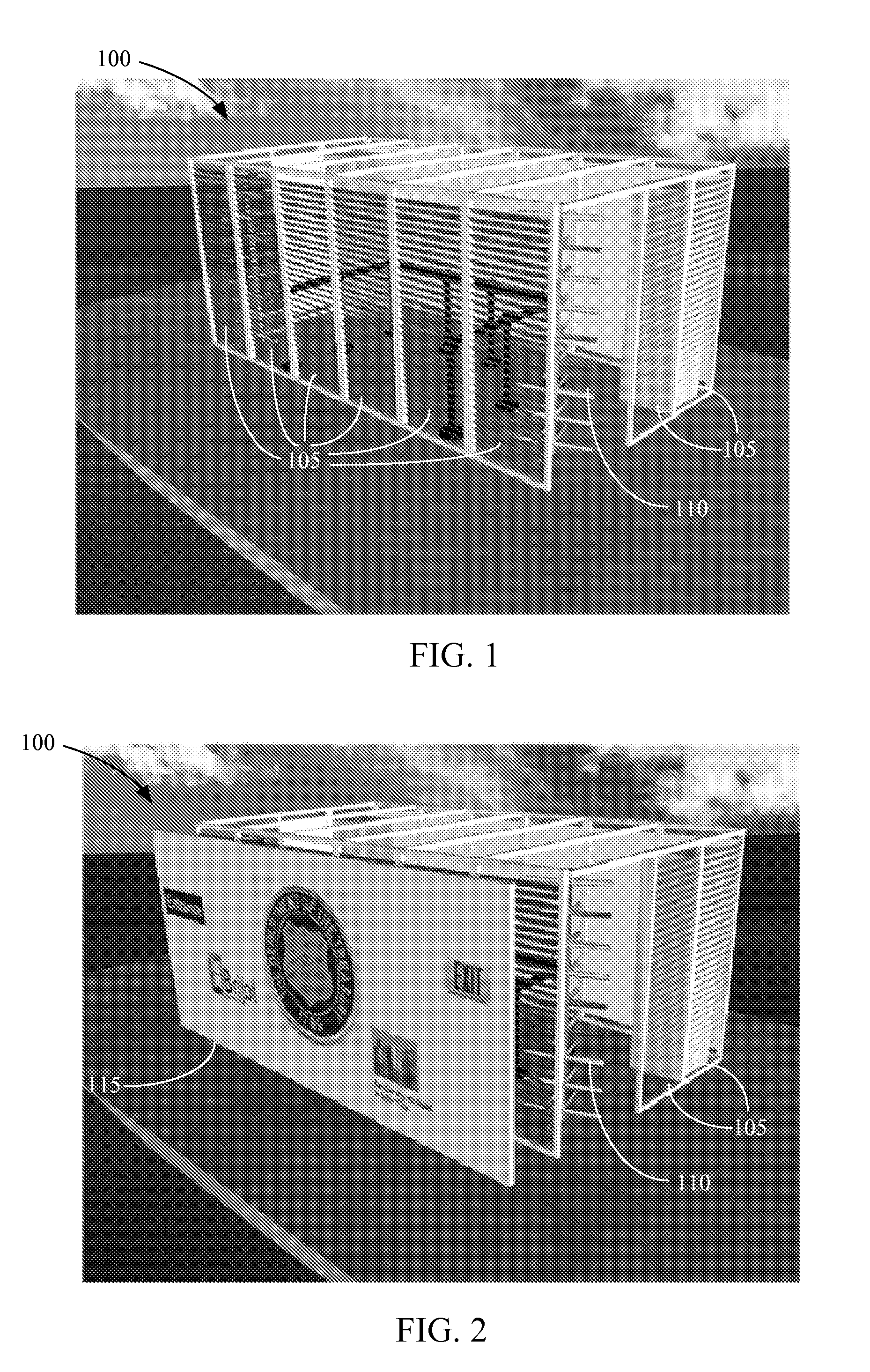
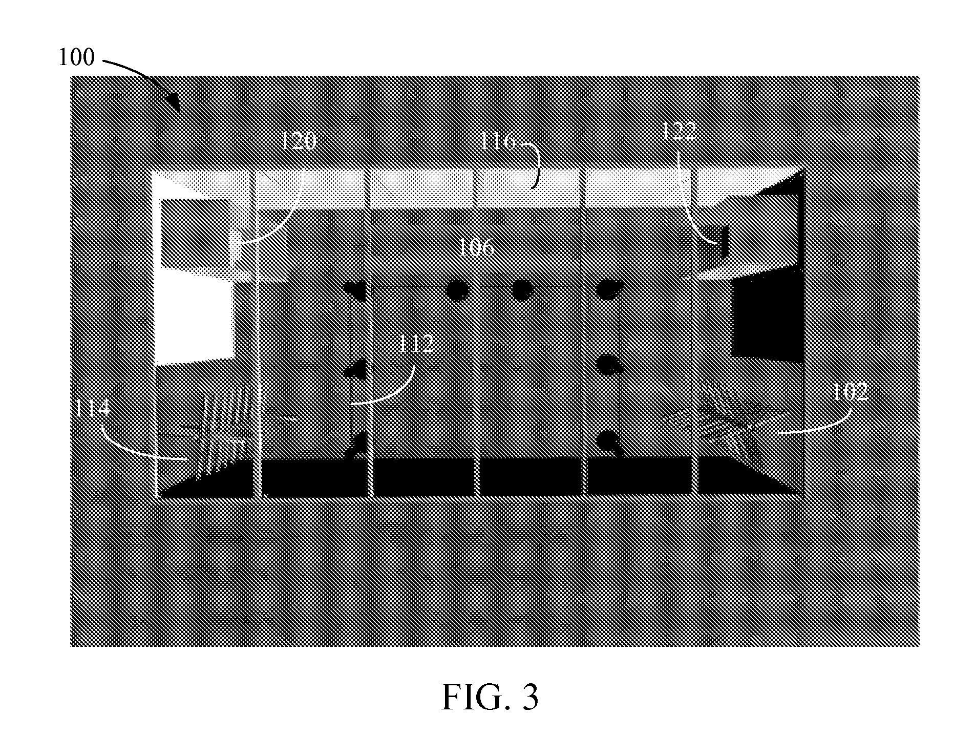
[0023]A system for deployment of a millimeter wave concealed object detection system using an outdoor passively illuminated structure is disclosed. The system provides effective control of deployment surroundings and provides a known and successful environment in which the millimeter wave equipment can operate. Several components, techniques, technologies and methodologies including, external millimeter wave energy mitigation, peripheral motion or clutter mitigation, test subject isolation, motion and flow control, threat containment, weather protection, decorative presentation, blast mitigation, and others may each be used separately, or in combination, with the system.

[0024]The system may employ a passively outdoor millimeter wave illuminator panel as described in U.S. Patent Application No. 60 / 917,414 filed May 11, 2007, the entire disclosure of which is incorporated herein by reference. In addition, the system may include complementary security technology or products including m...


PUM


Abstract

A system for deployment of a millimeter wave concealed object detection system using an outdoor passively illuminated structure is disclosed. In a particular embodiment, the structure includes at least one sidewall with at least one louvered panel within the sidewall. The louvered panel is orientated to reflect millimeter energy into the structure that is used in part by a concealed object detection system for detecting concealed objects. The louvered panel includes a plurality of adjustable parallel slats for obtaining an optimum deployment angle. The structure further includes at least one detection lane for guiding a subject through the structure and is configured between a controlled entry barrier and an exit barrier of the structure.

Description

I. CROSS REFERENCE TO RELATED APPLICATIONS[0001]This application claims the benefit of U.S. Provisional Application No. 60 / 942,480 filed Jun. 7, 2007. The disclosure of the provisional application is incorporated herein by reference. In addition, this application relates to the subject matter of U.S. Provisional Patent Application No. 60 / 917,414 filed May 11, 2007, and U.S. Provisional Patent Application No. 60 / 914,332 filed Apr. 27, 2007, the entire disclosures of which are incorporated herein by reference.II. FIELD[0002]The present disclosure relates generally to the field of deployment systems, and in particular to a system for deployment of a millimeter wave concealed object detection system using an outdoor passively illuminated structure.III. DESCRIPTION OF RELATED ART[0003]Security systems can be found at airports, train stations, arenas, construction sites, and other public, private, commercial and industrial facilities. In addition, security systems are used in field milita...

Claims


Application Information

Patent Timeline
Patent Type & Authority Applications(United States)
IPC IPC(8): G01S13/04
CPCG01S13/887E04H1/12
Inventor DALY, ROBERT PATRICKREINPOLDT, WILLEM H.
Owner MICROSEMI
Why Eureka
Try Eureka