Portable robot

a robot and portability technology, applied in the field of portable robots, can solve the problems of large number of costly jigs, high investment requirements for these machines, and present a series of operational limitations, so as to improve productivity, improve the portability of the robot, and simplify the training of the operator.

Inactive Publication Date: 2013-01-08
AIRBUS OPERATIONS SL
View PDF8 Cites 4 Cited by
  • Summary
  • Abstract
  • Description
  • Claims
  • Application Information

AI Technical Summary

Benefits of technology

[0005]The manual processes are deficient in terms of productivity and overall process cost, and so automation processes are gradually being introduced for carrying out the drilling in such a way that the drilling times are reduced. It can be pointed out that this process of the assembly process lasts a long time since each product typically has thousands of holes, which means that total savings in production time can be notable.
[0010]For this reason, the invention has developed a new automated drilling robot that is portable and of small dimensions. As a result of this portability of the robot, the piece can remain in a fixed location and does not require any specific or permanent foundation for the machine in the production plant.
[0011]Moreover, the inventive robot does away with a large part of the referencing and adjustment times of the machine to the product, for which it provides the portable system with the capacity for fixing itself to the assembly stand of it. Also, the inventive robot improves productivity since it is capable of carrying out all the work on the same product automatically without any intervention from the operator, in such a way that it moves under its own means over the whole of the stand in order to traverse the different work zones until it covers the entire extent of the product.
[0012]Furthermore, by means of the inventive robot, the training of the operators becomes simpler, and it also requires much less configuration than conventional machines, which means that its starting cost is much less. The invention also permits itself to be adjusted to different sets of stands and facilitates its use in the production plant, with which the dead times of this system are far fewer than those of the conventional version. All this leads to the amortisation of the robot in much shorter time spans.

Problems solved by technology

For this, a large number of costly jigs are used for the precision positioning of the manual or semi-automatic tools used by operators for carrying out the drilling.
The investments required for these machines are generally fairly high and they are present a series of operational limitations.
This type of machinery requires a large amount of permanent floor space and it also requires the product to be processed, along with its tool, to be brought to the work zone of the machine.
In addition to this drawback, its size and large work volumes makes it difficult for this type of machine to maintain narrow positioning tolerances throughout its entire range of movement in all its axes, since it has to perform thousands of drill-holes from its fixed location, in which the holes at one end are separated from those at the other end by very considerable distances.
The need therefore arises to reference and calibrate the machine to the piece several times during the work process, which has a significant negative impact on the total efficiency and on the cost of the process.
As a consequence, considering the progressive increase in aeronautical structural components that is being witnessed in recent times, it seems evident that traditional fixed machinery is destined to become less and less suitable owing to the fact that the large dimensions of these components have a direct influence both on the performance of the machine and on the cost of the system.

Method used


Image

  • Portable robot
  • Portable robot
  • Portable robot

Examples


Embodiment Construction

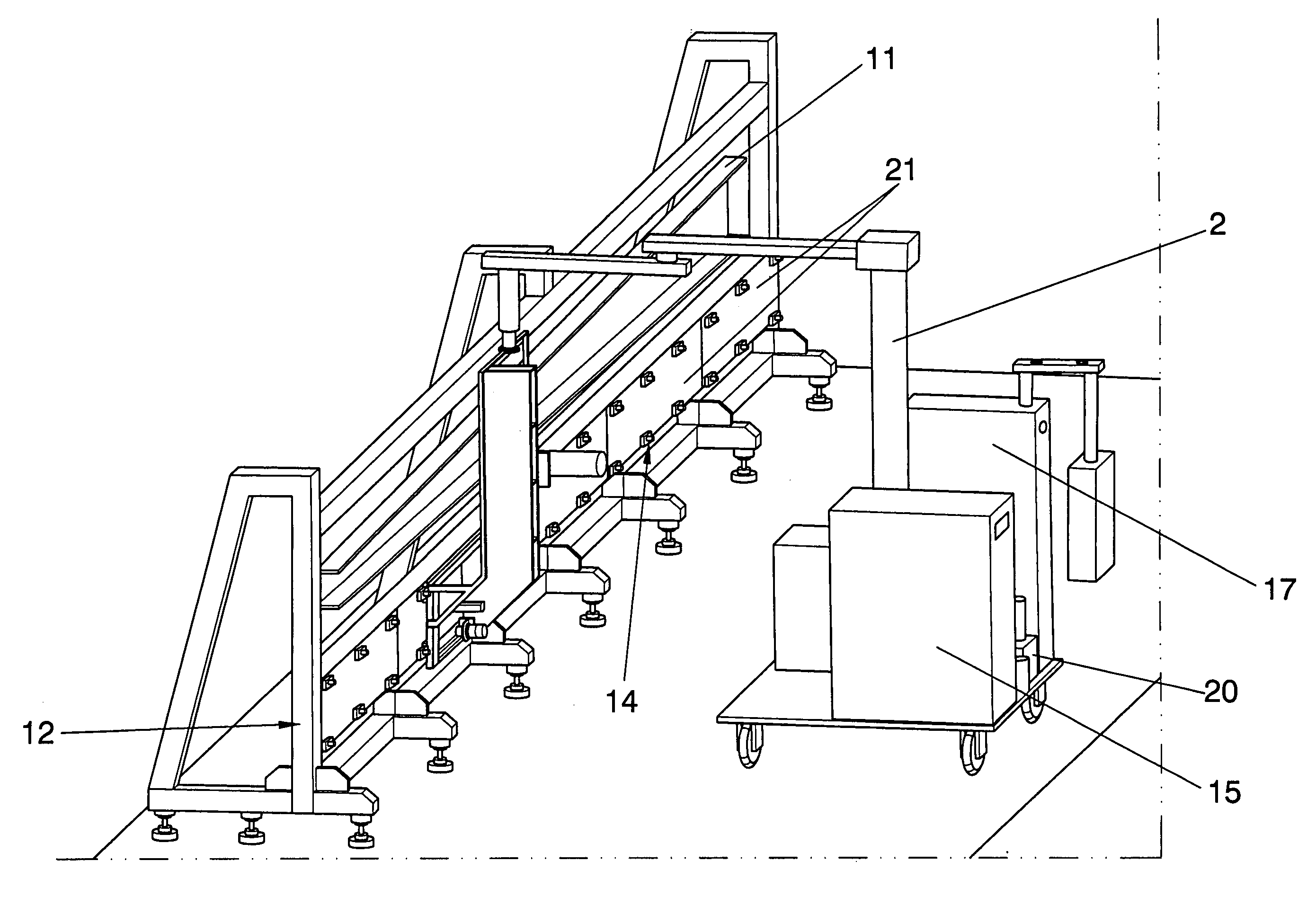
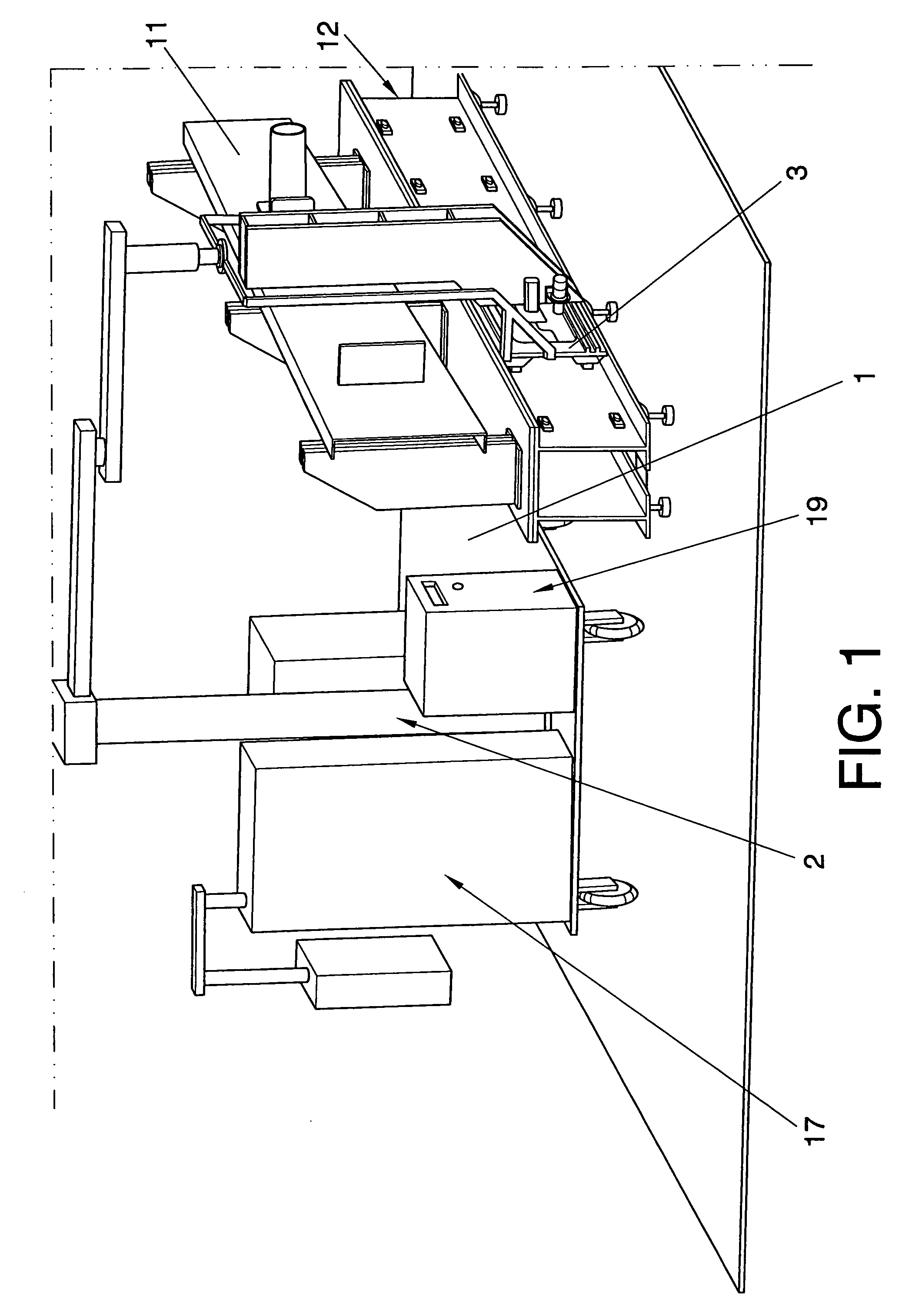
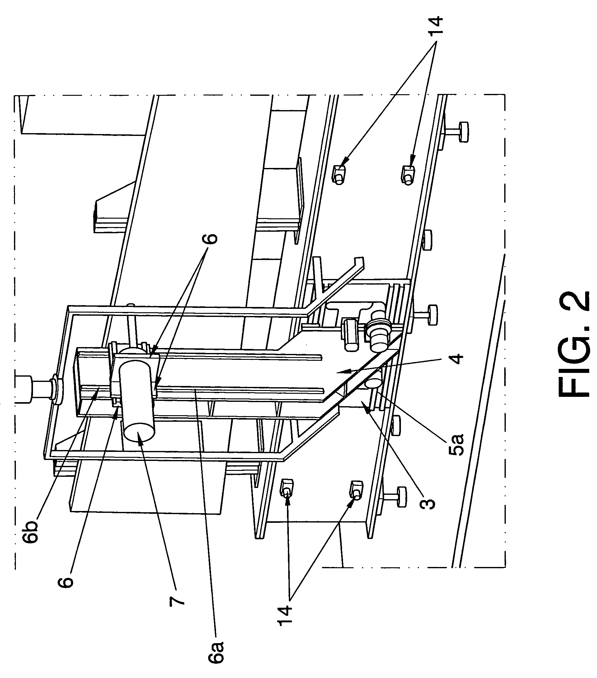
[0015]As it has been described, the portable robot of the invention is intended to carry out the drilling process in the assembly process of aeronautical components which, by means of precision tools, are secured on a support known as a stand; and which is characterised in that it comprises a displaceable platform in order to permit it to be located close to the stand, and in which an arm is included which supports a frame comprising a beam intended to support a drilling head that can be displaced in the three axes. It also comprises means of securing the frame to the stand in at least one position required in said stand, from which the displacement of the head along the three axes is governed by means of numerical control in order to carry out the drillings previously established in the numerical control. Consequently, this structure permits the frame to be secured to the stand and from this point the functioning of the head in the three axes is governed. This means that the robot ...


PUM

PropertyMeasurementUnit
displacementaaaaaaaaaa
sizeaaaaaaaaaa
flexibilityaaaaaaaaaa

Abstract

Portable robot for carrying out the drilling process in the assembly of aeronautical components which are secured on a support known as a stand. The robot comprises a displaceable platform in order to permit it to be located close to the stand, and an arm, which supports a frame comprising a beam intended to support a drilling head that can be displaced in the three axes.

Description

OBJECT OF THE INVENTION[0001]The portable robot of the invention is intended to carry out the drilling process undertaken during the fitting or assembly of aeronautical components, for which these components are fitted by means of precision tools on a support conventionally known as a stand; and which has the object of allowing the robot to displace itself to the place where the stand is to be found, on which it is fixed in order to produce the different drill-holes.[0002]Another object of the invention is to allow the robot to be able to advance automatically along those stands, securing itself in different positions provided therein in order to produce all the drill-holes for the piece to fit.[0003]In particular, the invention is applicable to the drilling carried out in the assembly of large aeronautical structures such as wing spars, stabilisers and control surfaces, but it can obviously be used in the assembly of any of the pieces of an aircraft. The invention is furthermore ap...

Claims


Application Information

Patent Timeline
Patent Type & Authority Patents(United States)
IPC IPC(8): B23P23/00B23B39/00B23Q3/157
CPCB23B41/006B23Q9/0014B25J15/0095B23B2215/04Y10T409/306384Y10T408/554Y10T29/5108Y10T408/5623Y10T408/5612Y10T29/5118Y10T483/1736Y10T408/563Y10T408/56245
Inventor GONZALEZ SAINZ, JAVIERASTORGA RAMIREZ, JUAN RAMONSAENZ FERNANDEZ, AGUSTIN J.COLLADO JIMENEZ, VALENTIN
Owner AIRBUS OPERATIONS SL
Why Eureka
Try Eureka