Laser machine

a laser machine and nozzle tip technology, applied in metal-working equipment, welding equipment, manufacturing tools, etc., can solve the problems of reducing the degree of enclosure of the nozzle tip body, reducing the drilling time, and reducing the difficulty of removing melted materials

Active Publication Date: 2020-02-18
FANUC LTD
View PDF33 Cites 3 Cited by
  • Summary
  • Abstract
  • Description
  • Claims
  • Application Information

AI Technical Summary

Benefits of technology

[0009]In consideration with such circumstance, the present invention has an object to provide a laser machine capable of reliably drilling a small hole in a workpiece when drilling of the workpiece is performed, capable of reducing drilling time even when the workpiece is thick, or the like, and capable of preventing an optical system from being contaminated by a melted material.
[0013](4) In the laser machine of any of (1) to (3), a gas layer (for example, a gas layer 11 described later) that prevents the gas from intruding between the optical system and the gas flow path, so that the gas supplied along the gas flow path does not reach the optical system.
[0016](7) In the laser machine of any of (1) to (6), in the nozzle, the tip end of the nozzle tip body is provided with the elastic member (for example, an elastic member 30 described later) that contacts with the workpiece and improves the degree of enclosure of the nozzle tip body by the workpiece.
[0017]By the present invention, when drilling of a workpiece is performed by using a laser machine, by gas flow crossing across a laser beam, a negative pressure is generated in a laser received area of the workpiece, and a melted material is sucked and removed. As a result, a small hole can be reliably drilled in the workpiece, and drilling time can be reduced even when the workpiece is thick, or the like. Further, an optical system can be prevented from being contaminated by the melted material.

Problems solved by technology

However, this is inconvenient as follows.
First, there is a risk that, when a small hole is opened, due to influence of the assist gas, not only the laser received area of the workpiece but also a peripheral region thereof is deformed or removed by thermal conduction from the melted material, and the hole diameter becomes larger than that is intended.
Second, when the workpiece is thick or high in specific gravity (hereinafter, referred to as “when the workpieces is thick, or the like”), in a process of drilling by laser processing, the melted material becomes difficult to be removed and drilling takes much time.
Third, in drilling of the workpiece, the laser received area of the workpiece is heated suddenly, and the temperature of the workpiece exceeds instantaneously the melting point and the boiling point.
Thus, the melted material splashes to a laser irradiating direction and contaminates an optical system such as a lens and a window.

Method used


Image

  • Laser machine
  • Laser machine
  • Laser machine

Examples


first embodiment

Modification of First Embodiment

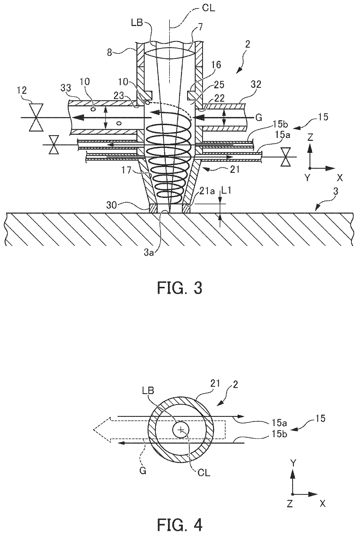
[0043]FIG. 3 is a vertical cross section view showing the nozzle of a laser machine according to a modification of a first embodiment. FIG. 4 is a horizontal cross section view showing the nozzle of the laser machine according to the modification of the first embodiment.

[0044]The laser machine 1 according to this modification of the first embodiment has a different configuration of the nozzle 2 from that of the first embodiment described above, as follows. Other configurations are basically similar to those of the first embodiment described above. Thus, the same members are added with the same numerals, and description thereof is omitted.

[0045]As shown in FIG. 3 and FIG. 4, in the nozzle 2 of this laser machine 1, an airflow generator 15 that generates a helical rising airflow in the inside of the nozzle tip body 21 is attached to the nozzle tip body 21. This airflow generator 15 is composed of a first gas path 15a that sends air substantially horizon...


PUM

PropertyMeasurementUnit
thicknessaaaaaaaaaa
core diameteraaaaaaaaaa
length L2aaaaaaaaaa

Abstract

To provide a laser machine capable of reliably drilling a small hole when drilling of the workpiece is performed. A laser machine 1 includes: a laser oscillator; a light guide path; a processing head; and a nozzle. The nozzle includes: a nozzle tip body that irradiates the workpiece with the laser beam; a charge port formed in the nozzle tip body; and an exhaust port formed in the nozzle tip body so as to oppose to the charge port. The nozzle supplies gas to the inside of the nozzle tip body along a gas flow path extending from the charge port to the exhaust port in a form of crossing across the laser beam in the nozzle tip body, to generate a negative pressure in the vicinity of an opening part of a tip end of the nozzle tip body.

Description

[0001]This application is based on and claims the benefit of priority from Japanese Patent Application No. 2017-007925, filed on 19 Jan. 2017, the content of which is incorporated herein by reference.BACKGROUND OF THE INVENTIONField of the Invention[0002]The present invention relates to a laser machine.Related Art[0003]Conventionally, when drilling is performed by using a laser machine, in order to blow away and remove a melted material generated in a laser light received area of a workpiece, and accelerate combustion of the workpiece, assist gas such as nitrogen and oxygen is blown to the laser light received area of the workpiece coaxially with a laser beam (refer to Patent Document 1 as an example).[0004]Patent Document 1: Japanese Unexamined Patent Application, Publication No. 2013-27907SUMMARY OF THE INVENTION[0005]However, this is inconvenient as follows.[0006]First, there is a risk that, when a small hole is opened, due to influence of the assist gas, not only the laser recei...

Claims


Application Information

Patent Timeline
Patent Type & Authority Patents(United States)
IPC IPC(8): B23K26/362B23K26/14B23K26/21B23K26/142B23K26/382B23K26/38B23K26/16
CPCB23K26/21B23K26/14B23K26/382B23K26/1464B23K26/1476B23K26/142B23K26/702B23K26/16
Inventor IZUMI, TAKASHI
Owner FANUC LTD
Why Eureka
Try Eureka