Heat dissipating structure for electronic component and display device

a technology of electronic components and heat dissipation structures, which is applied in the direction of lighting, heating apparatus, and electric apparatus casings/cabinets/drawers, etc., can solve the problems of difficult efficient heat dissipation, large number of heat-emitting components, and complex arrangement of heat pipes, so as to improve the quiet of cooling fans and reduce noise. , the effect of simple structur

Inactive Publication Date: 2009-06-04
SONY CORP
View PDF7 Cites 13 Cited by
  • Summary
  • Abstract
  • Description
  • Claims
  • Application Information

AI Technical Summary

Benefits of technology

[0006]However, in a display device of a small television receiver, for example, a large number of electronic components are densely disposed inside the main body, each electronic component individually emitting heat, and thus, resulting in a large number of heat-emitting components existing in mixture inside the main body. In such a case, when trying to dissipate the heat emitted by each electronic component with a heat pipe, the arrangement of the heat pipes becomes complicated, making difficult to efficiently dissipate heat. Thus, particularly in a small television receiver or the like, there occurs a problem that the temperature inside the main body of the display device easily rises.

Problems solved by technology

However, in a display device of a small television receiver, for example, a large number of electronic components are densely disposed inside the main body, each electronic component individually emitting heat, and thus, resulting in a large number of heat-emitting components existing in mixture inside the main body.
In such a case, when trying to dissipate the heat emitted by each electronic component with a heat pipe, the arrangement of the heat pipes becomes complicated, making difficult to efficiently dissipate heat.
Thus, particularly in a small television receiver or the like, there occurs a problem that the temperature inside the main body of the display device easily rises.
However, with the method of attaching a rubber cushion at the fitting portion for the cooling fan, a comparatively large area is required for the space of the rubber cushion, and thus, it is particularly not suited for a small device.
Further, with the method of attaching a rubber cushion, there is a problem that the number of components increases and the procedure of fitting the cooling fan becomes complicated.

Method used


Image

  • Heat dissipating structure for electronic component and display device
  • Heat dissipating structure for electronic component and display device
  • Heat dissipating structure for electronic component and display device

Examples


Embodiment Construction

[0027]Hereinafter, preferred embodiments of the present invention will be described in detail with reference to the appended drawings. Note that, in this specification and the appended drawings, structural elements that have substantially the same function and structure are denoted with the same reference numerals, and repeated explanation of these structural elements is omitted.

[0028][Overall Structure of Display Device]

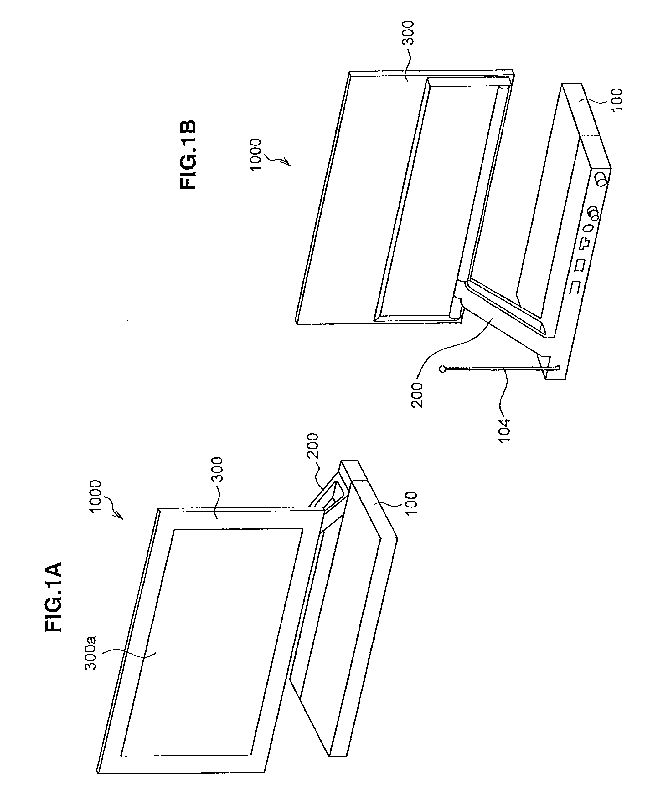
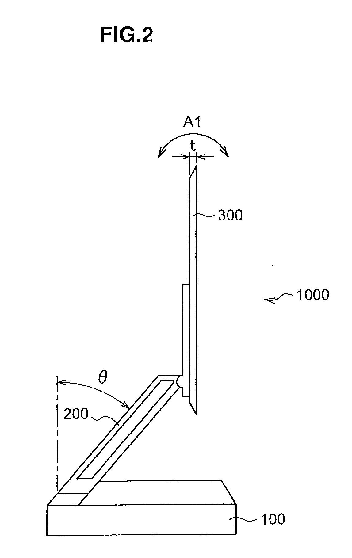
[0029]FIGS. 1A and 1B are schematic perspective views showing appearances of a display device 1000 according to an embodiment of the present invention. Here, FIG. 1A is a schematic perspective view showing the display device 1000 seen from the front upper right. Further, FIG. 1B is a schematic perspective view showing the display device 1000 seen from the back upper right. Further, FIG. 2 is a schematic perspective view showing the display device 1000 seen from the front left side.

[0030]As shown in FIGS. 1A, 1B and 2, the display device 1000 of the present embodimen...


PUM


Abstract

A heat dissipating structure for an electronic component of the present invention includes a main board on which electronic components are mounted, a heat sink disposed facing the main board and contacting a plurality of the electronic components on the main board, a heat pipe disposed on the heat sink, an arm branching from the heat sink and elastically deformable in relation to the heat sink, and a cooling fan located at the end portion of the heat pipe.

Description

CROSS REFERENCES TO RELATED APPLICATIONS[0001]The present invention contains subject matter related to Japanese Patent Application JP 2007-308282 filed in the Japan Patent Office on Nov. 29, 2007, the entire contents of which being incorporated herein by reference.BACKGROUND OF THE INVENTION[0002]1. Field of the Invention[0003]The present invention relates to a heat dissipating structure for an electronic component and a display device.[0004]2. Description of the Related Art[0005]In related art, in a personal computer, for example, to suppress heat emitted by an electronic component disposed in the main body thereof, heat emitted by a specific electronic component is transferred by using a heat pipe to a cooling fan to be dissipated as described in JP-A-2002-76664.SUMMARY OF THE INVENTION[0006]However, in a display device of a small television receiver, for example, a large number of electronic components are densely disposed inside the main body, each electronic component individua...

Claims


Application Information

Patent Timeline
Patent Type & Authority Applications(United States)
IPC IPC(8): H05K7/20
CPCH05K7/2099
Inventor SAKATA, TATSUYAYAMAUCHI, TORUSEKI, KENICHIYANA, TERUTAKA
Owner SONY CORP
Why Eureka
Try Eureka