
Illumination Device for Kitchen Hood

a technology for illumination devices and kitchen hoods, which is applied in the field of illumination devices for kitchen hoods, can solve the problems of large energy consumption, insatisfactory illumination features of most users, and blurred light cases, and achieve the effect of optimal illumination features

Inactive Publication Date: 2009-06-04
LAN SHIH CHI +1
View PDF5 Cites 119 Cited by
  • Summary
  • Abstract
  • Description
  • Claims
  • Application Information

AI Technical Summary

Benefits of technology

[0010]The primary object of the present invention is to provide an illumination device for a kitchen hood and the heat from the light unit is directly conducted to the light case and the hood so that the heat can easily escape from the light unit. The light unit is further cooperated with a bulb shade which includes a refraction portion, a reflection portion so as to provide optimal illumination feature.

Problems solved by technology

The conventional tin-filament light bulbs require a lot of energy and generate high heat which makes the light cases to be blurred.
The illumination feature is not satisfied by most users.
Besides, the conventional illumination device occupies a lot of space which makes the conventional hood to be bulky and ugly.
It is experienced that the halogen light bulbs generate even higher temperature which might be hurt the users and shortens the life of the halogen light bulbs.
Nevertheless, the individual conventional light emitting diode cannot provide sufficient illumination so that multiple light emitting diodes have to be arranged together.
Furthermore, the light beam is narrow and can only illuminate a small area.
The operation temperature does not burn the light emitting diodes and the problem for the conventional light emitting diodes is the less illumination.

Method used


Image

  • Illumination Device for Kitchen Hood
  • Illumination Device for Kitchen Hood
  • Illumination Device for Kitchen Hood

Examples


Embodiment Construction

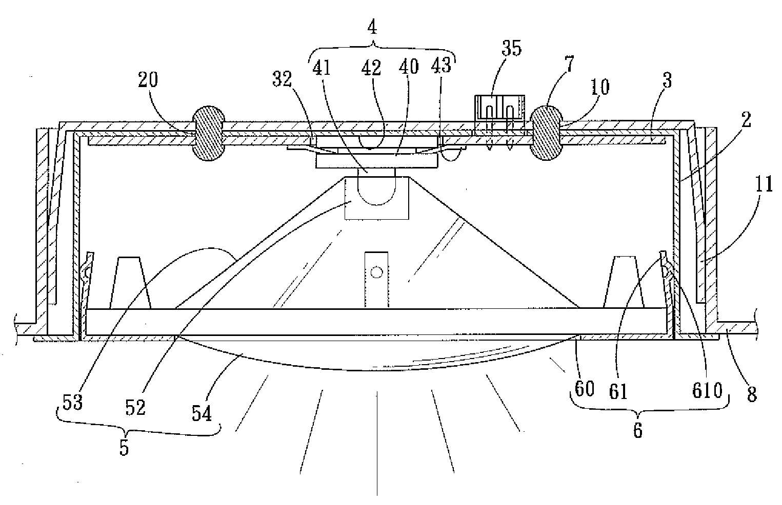
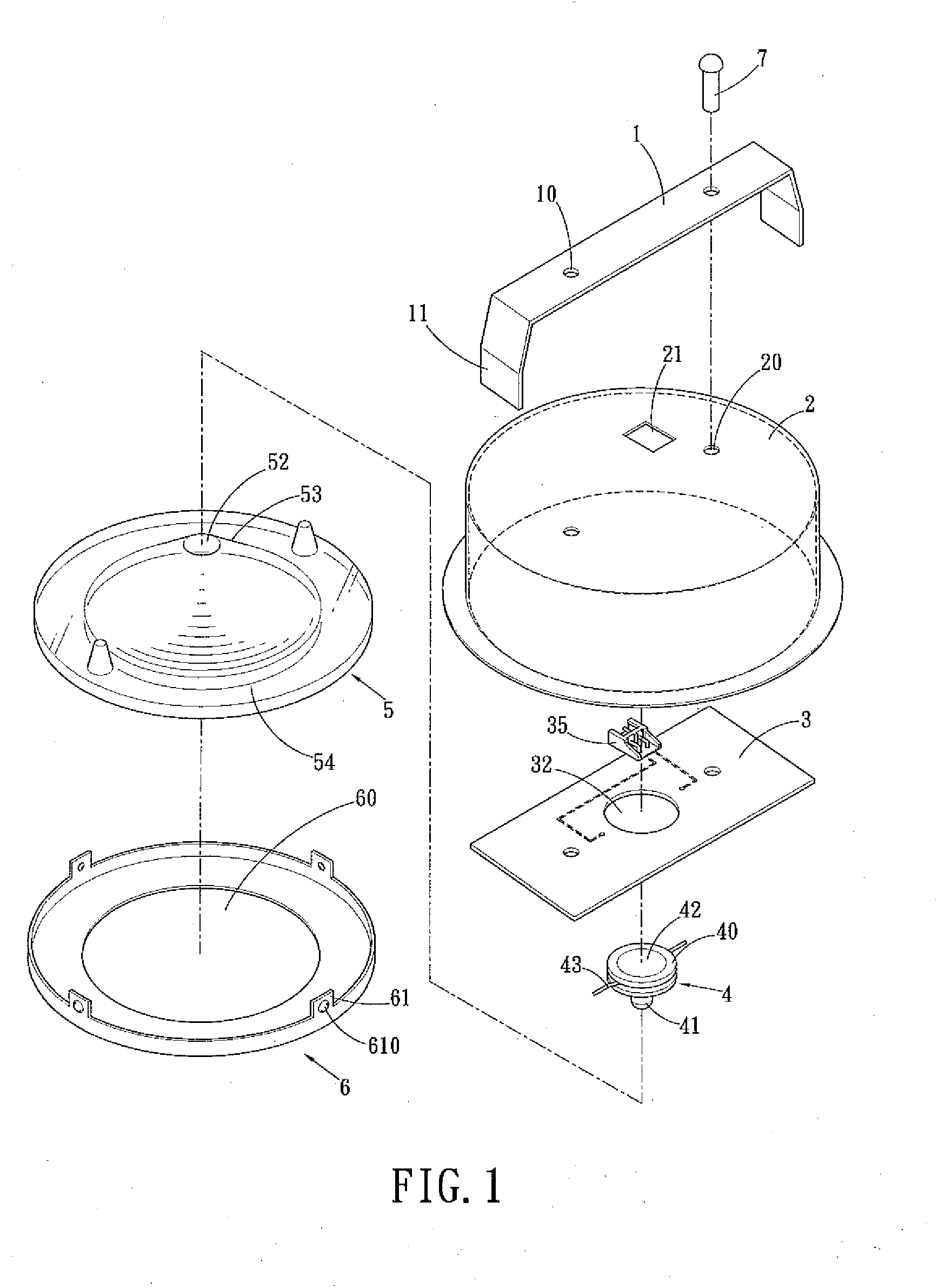
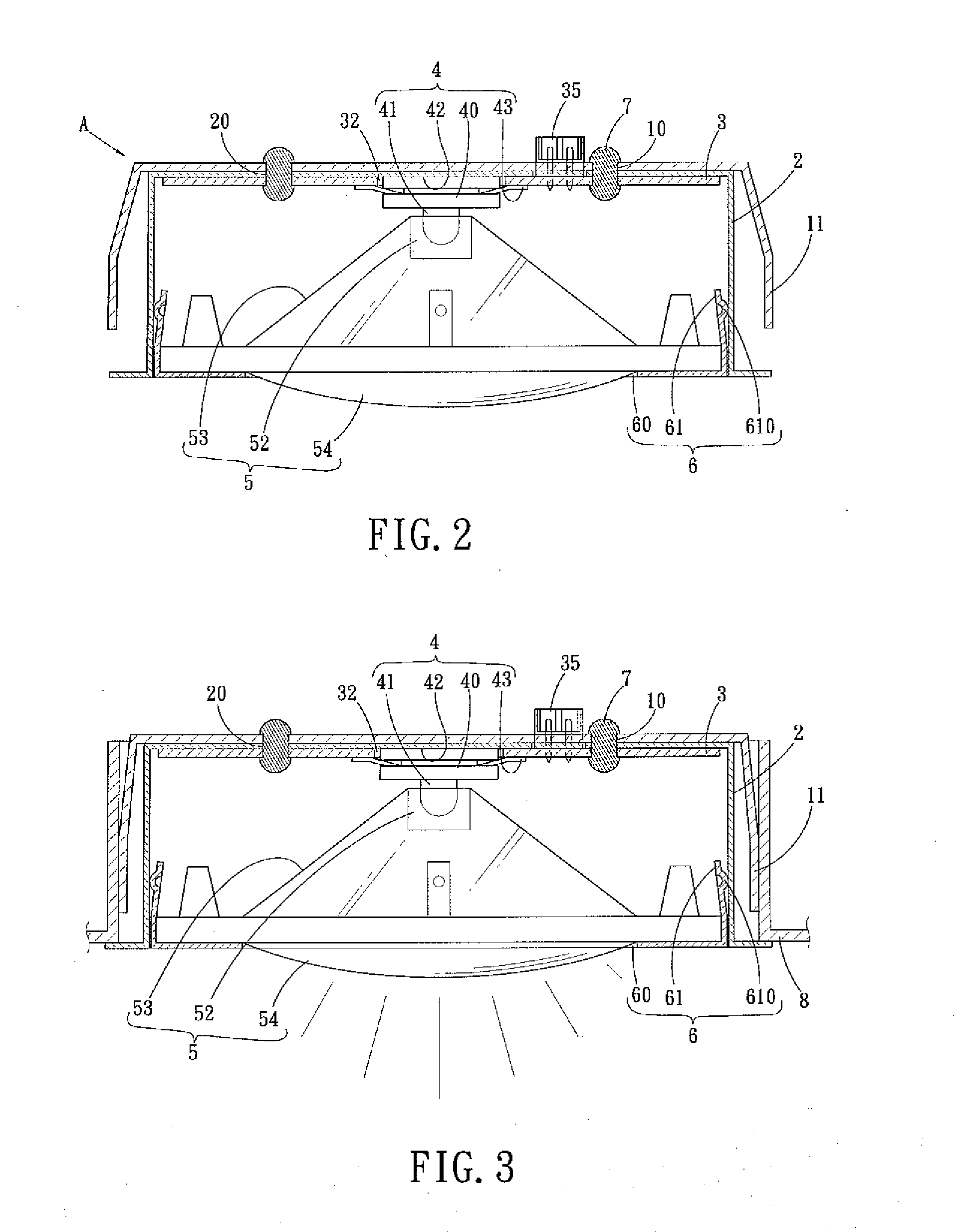
[0020]Referring to FIGS. 1 to 8, the illumination device “A” for a kitchen hood 8 of the present invention comprises a flexible plate 1 which is mounted onto a light case 2 and a circuit board 3 is connected to an inside of the light case 2. The light case 2 is made by high heat conductive material so as to quickly transfer heat away. The light case 2 includes an open bottom with which a cover 6 is engaged. The cover 6 is a loop-like member and includes an opening 60 and four lugs 61 extend perpendicularly from a periphery of the cover 6. Each lug 61 includes a protrusion 610 and is flexible so that the lugs 61 can be inserted to the inner periphery of the light case 2 and the protrusions 610 enhance the connection between the lugs 61 and the light case 2.

[0021]A terminal 35 is connected to the circuit board 3 and extends through a through hole 21 defined through a top of the light case 2 so that the terminal 35 is located outside of the light case 2. A light unit 4 is connected to ...


PUM


Abstract

An illumination device for a kitchen hood includes a light case made by high heat conductive material and a circuit board is connected to an inside of the light case. A terminal is connected to the circuit board and located outside of the light case. A light unit is connected to the circuit board and located in the light case. The light unit directly contacts the inside of the light case so as to conduct the heat from the light unit to the light case. The light case includes an open bottom with which a cover is engaged and a bulb shade is located between the light unit and the cover so as to focus or guide the light beam from the light unit.

Description

BACKGROUND OF THE INVENTION[0001](1) Field of the Invention[0002]The present invention relates to an illumination device for a kitchen hood and uses high efficiency light emitting diodes whose heat dispensing areas contact the light case which is made by highly heat conductive material.[0003](2) Description of the Prior Art[0004]A conventional illumination device for kitchen hood generally uses tin-filament light bulbs which are enclosed by light cases so as to prevent grease from attaching the light bulbs. The conventional tin-filament light bulbs require a lot of energy and generate high heat which makes the light cases to be blurred. The illumination feature is not satisfied by most users. Besides, the conventional illumination device occupies a lot of space which makes the conventional hood to be bulky and ugly. Some hook manufacturers use halogen light bulbs to provide higher illumination.[0005]It is experienced that the halogen light bulbs generate even higher temperature whic...

Claims


Application Information

Patent Timeline
IPC IPC(8): F21V7/00B60Q1/00
CPCF21S8/02F21V15/01F21V29/004F21V33/0044F21V29/85F24C15/2064F21W2131/301F21V29/74F21Y2101/02F21Y2115/10F21V29/507F21W2131/30
Inventor LAN, SHIH-CHICHIEN, YUEH-LI
Owner LAN SHIH CHI
Learn More