
Eureka
For R&D, Eureka makes reading and utilizing patents & technical documents easy.
Eureka AIR
Designed for self-driven R&D workflows. Generate viable solutions, solve complex R&D challenges, empower your innovation with AI.

Eureka Materials
Designed for material experts only. Revolutionize your material R&D, from search, analyze, to developing new materials.

TechResearch
Generate reliable direction feasibility study reports for your R&D in just a few steps.

TechSeek
Discover and master advanced knowledge NOW. Basics, ideas, possibilities, all at once.

TechMind
As an expert in R&D Theories, TechMind can generates customized viable solutions instantly.

TechRisk
Analyze your overall solution with one click, know your potential R&D risks in advance.

TechMonitor
Get weekly tech updates, stay abreast of the latest tech innovations and key insights.
Auditory prosthesis utilizing intra-neural stimulation of the auditory nerve
- Summary
- Abstract
- Description
- Claims
- Application Information
AI Technical Summary
Problems solved by technology
Method used
Image

Examples
example 1
Materials and Methods
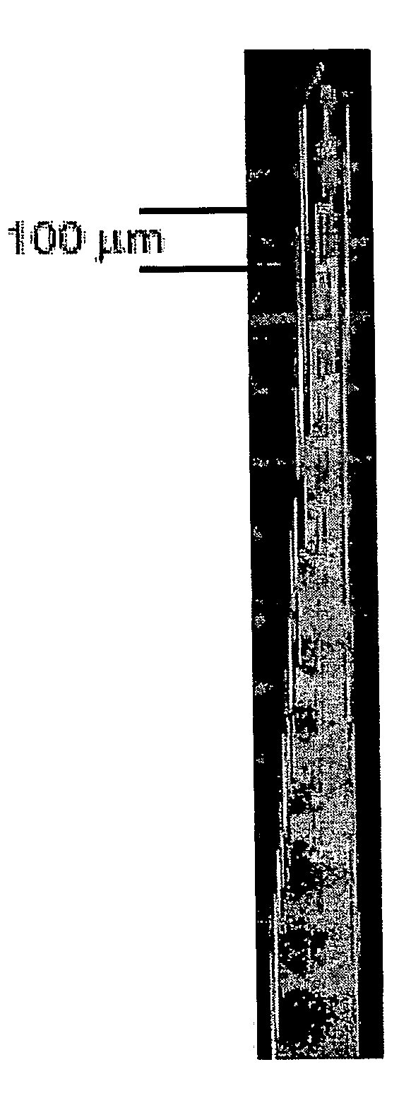
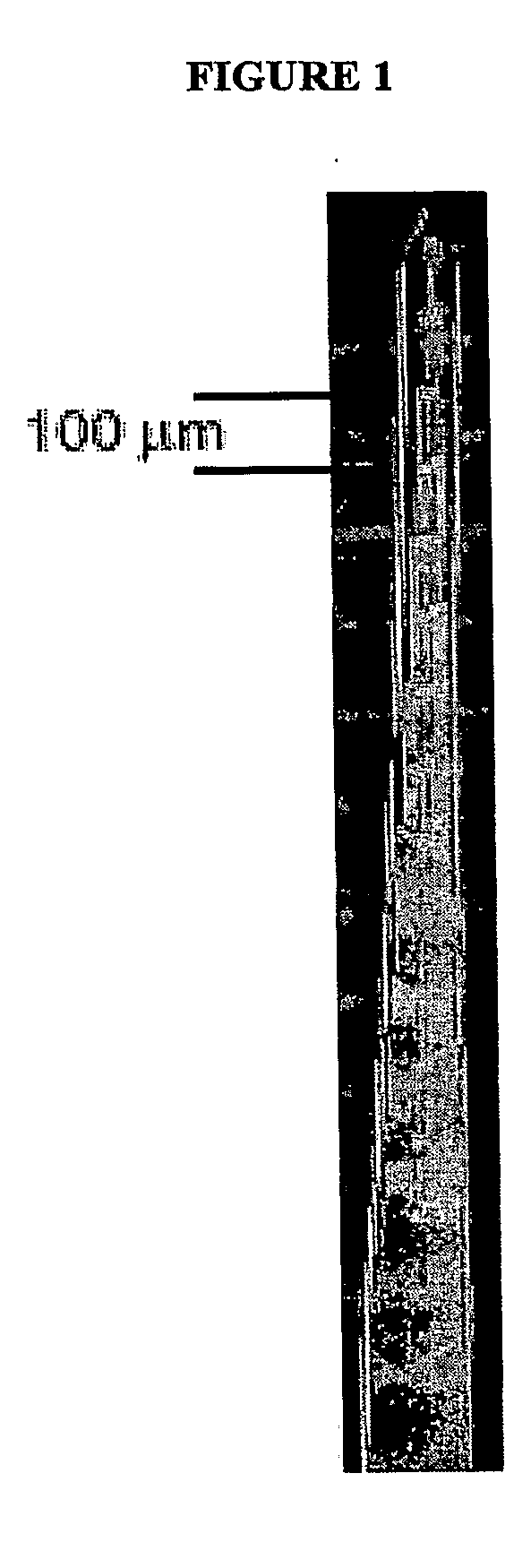
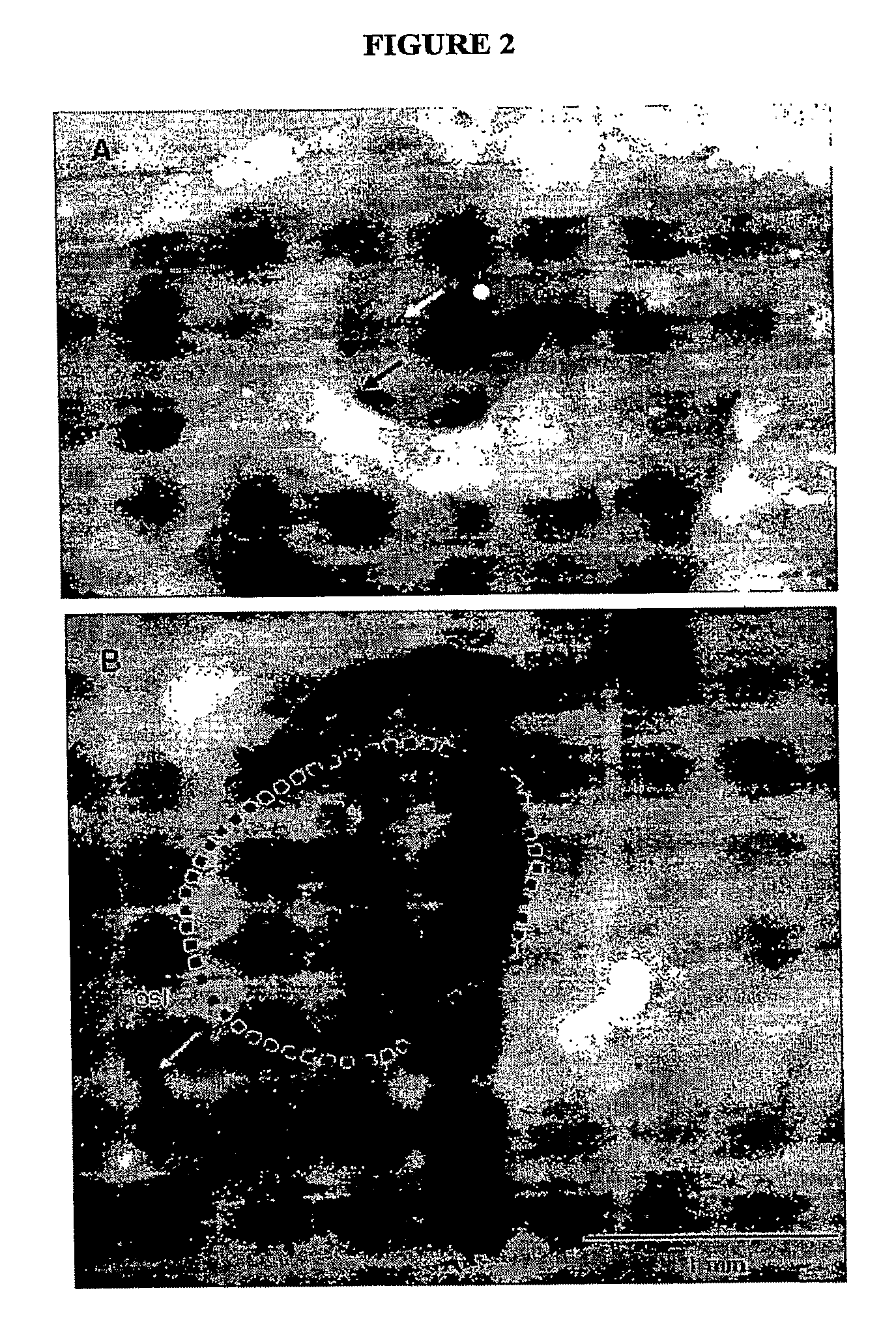
[0036]Experiments were conducted in barbiturate-anesthetized cats. Responses to acoustic tones, to electrical stimulation with a conventional cochlear implant, and to electrical stimulation with an intra-neural array were characterized. Neural activity was recorded from the inferior colliculus of the midbrain as a means of monitoring activation of the ascending auditory pathway. The right ear was deafened by disarticulation of the ossicles. The right inferior colliculus was visualized by aspiration of overlying occipital cortex. A 32 channel, silicon-substrate recording probe was inserted through the inferior colliculus oriented in the coronal plane and angled from dorsolateral to ventromedial at an angle of 45° from the mid-sagittal plane. This trajectory allowed the probe to span up to 6 octaves of the tonotopic organization of the colliculus from below 500 Hz to above 32 kHz, which is most of the normal range of hearing in the cat. The probe had 32 recording ...
example 2
Responses to Acoustic Stimulation
[0041]Responses to acoustical tones were used to identify the positions of recording sites relative to the tonotopic axis of the inferior colliculus and to characterize the spread of excitation by tones under normal-hearing conditions. The frequency tuning of responses to tones was similar to those commonly reported in the inferior colliculus. The tonotopic progression of characteristic frequencies (CFs) as a function of the relative depth in the IC (distance along the shank of the recording probe; See FIG. 3A) was consistent with the commonly reported tonotopic organization of the inferior colliculus. Responses to tones under normal-hearing conditions are shown in FIG. 3. Each of the panels B through H represents responses to tones at a particular frequency as indicated in each panel. Responses are shown in the form of Spatial Tuning Curves (STCs). In each STC, the vertical dimension represents depth in the inferior colliculus and the horizontal dim...
example 3
Inferior Colliculus Responses to Conventional Intra-Scalar Stimulation
[0042]Following recordings in normal-hearing conditions, the left cochlea was deafened, a conventional scala-tympani electrode array was implanted, and inferior colliculus responses to scala-tympani stimulation were recorded. Scala-tympani stimulation in the MP configuration produced broad activation of recording sites spanning the tonotopic axis. In FIGS. 4A and C, STCs show responses to monopolar (MP) stimulation through individual cochlear implant channels, MP3 (See FIG. 4A) and MP8 (See FIG. 4C). Stimulation of the most apical sites of this array even at the lowest current levels activated recording probe sites broadly distributed throughout the deepest half of the inferior colliculus, representing the high frequency basal cochlea. At stimulation levels only about 2 to 4 dB higher, neural activation spread to encompass the entire tonotopic axis of the inferior colliculus, including the representation of apical...
PUM
 Abstract
Description
Claims
Application Information
 - R&D Engineer
- R&D Manager
- IP Professional
- Industry Leading Data Capabilities
- Powerful AI technology
- Patent DNA Extraction
Browse by: Latest US Patents, China's latest patents, Technical Efficacy Thesaurus, Application Domain, Technology Topic, Popular Technical Reports.
© 2024 PatSnap. All rights reserved.Legal|Privacy policy|Modern Slavery Act Transparency Statement|Sitemap|About US| Contact US: help@patsnap.com