Method for treating ophthalmic lenses
a technology for ophthalmic lenses and treatment agents, which is applied in the direction of packaging goods, containers, applications, etc., can solve the problems of un uniform coating of the lens surface with the treatment agent, and achieve the effect of reducing the material handling steps and the accompanying costs
- Summary
- Abstract
- Description
- Claims
- Application Information
AI Technical Summary
Benefits of technology
Problems solved by technology
Method used
Image
Examples
first embodiment
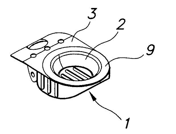
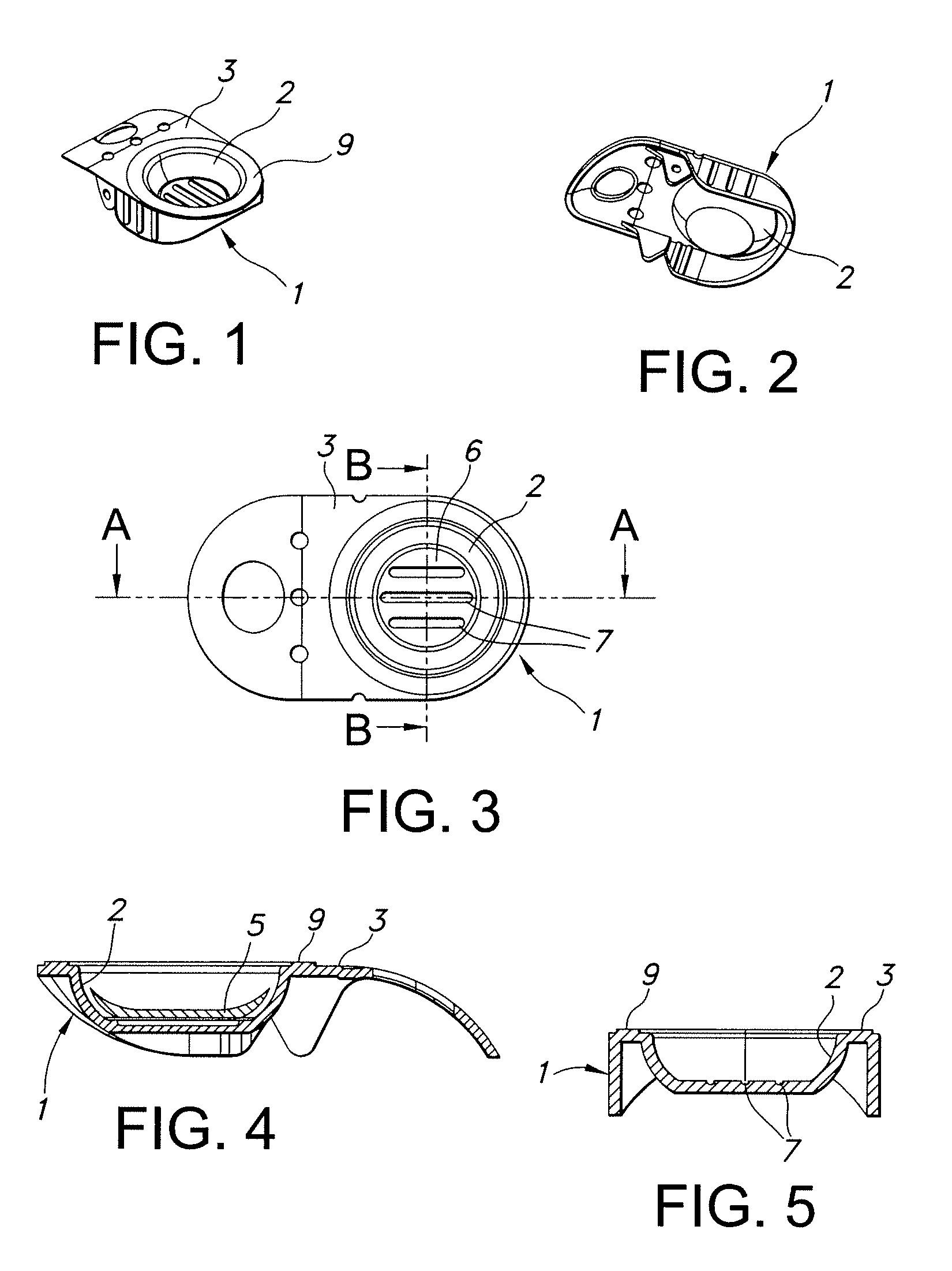
[0077]FIGS. 1 to 5 illustrate a blister package. Package 1 includes a substrate 3 including recess 2 formed therein, recess 2 sized and configured to hold an individual contact lens 5 therein. In the illustrated embodiment, recess 2 is a concave recess with a flat bottom 6. As seen in FIG. 4, the anterior surface of contact lens 5 rests on bottom 6 when the package is oriented as in FIG. 4. This can lead to non-uniform coating of the contact lens, especially this anterior surface of the lens resting on the recess bottom. These problems were overcome by employing packages with recesses including grooves in the bottoms thereof, to ensure better flow of the solution around the lens surfaces. Accordingly, bottom 6 includes three parallel, longitudinal grooves 7 therein. Grooves 7 preferably have a depth of at least 0.2 mm, more preferably at least 0.4 mm.
[0078]After contacting the contact lens with the treatment agent solution, contact lens 5 is contained in recess 2 and immersed in sol...
second embodiment
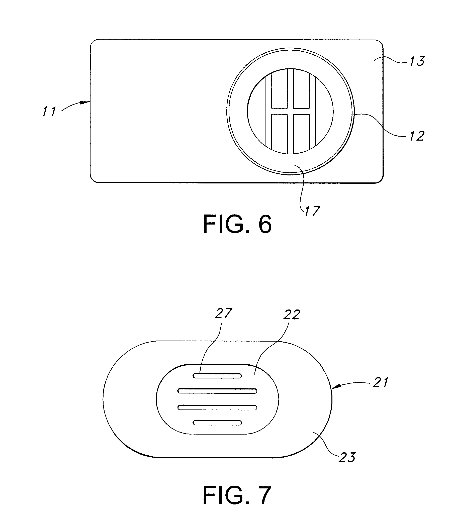
[0079]FIG. 6 illustrates a blister package. Package 11 includes a substrate 13 including recess 12 formed therein. In this illustrated embodiment, recess 12 is a concave recess, i.e., a rounded bowl shape. The bottom includes three interconnected, longitudinal grooves 17 therein.
third embodiment
[0080]FIG. 7 illustrates a blister package. Package 21 includes a substrate 23 including recess 22 formed therein. In this illustrated embodiment, recess 22 has a somewhat oval-shaped flat bottom, and the bottom includes four longitudinal grooves 27 therein.
[0081]Once the package recess contains the contact lens immersed in the final packaging solution, the recess is then sealed with lidstock, i.e., by sealing the lidstock with heat. As an example, the lidstock is sealed to raised surface 9 in FIGS. 1 to 5. The package and its contents may now be sterilized, preferably by heat sterilization such as autoclaving. The recess has a depth greater than a height of the lens, and a sufficiently large volume, that the lens is completely immersed in the final packaging solution. Preferably, the recess is filed with at least 0.5 ml of final packaging solution, more preferably at least 1 ml, and most preferably at least 1.2 ml.
PUM
| Property | Measurement | Unit |
|---|---|---|
| Volume | aaaaa | aaaaa |
| Volume | aaaaa | aaaaa |
| Depth | aaaaa | aaaaa |
Abstract
Description
Claims
Application Information
 - R&D
- Intellectual Property
- Life Sciences
- Materials
- Tech Scout
- Unparalleled Data Quality
- Higher Quality Content
- 60% Fewer Hallucinations
Browse by: Latest US Patents, China's latest patents, Technical Efficacy Thesaurus, Application Domain, Technology Topic, Popular Technical Reports.
© 2025 PatSnap. All rights reserved.Legal|Privacy policy|Modern Slavery Act Transparency Statement|Sitemap|About US| Contact US: help@patsnap.com


