High-Rise Aerial Apparatus and Vehicle Equipped Therewith

a technology for aerial apparatuses and high-rise buildings, which is applied in the direction of lifting devices, item transportation vehicles, building scaffolds, etc., can solve the problems of complex apparatuses, user injury risks, and difficulty in using such high-rise aerial apparatuses

Inactive Publication Date: 2009-06-11
GIMAEX INT
View PDF23 Cites 4 Cited by
  • Summary
  • Abstract
  • Description
  • Claims
  • Application Information

AI Technical Summary

Benefits of technology

[0015]The aim of the present invention is consequently to provide improved high-rise ae

Problems solved by technology

However, the use of such high-rise aerial apparatus can prove difficult or even dangerous when the base thereof is placed on a support that is not level, the degree of inclination or off-level being able to be accentuated at the free end of the elongate member, notably as a function of the elevation and/or extension thereof.
However, this apparatus is complex.
Further, a certain degree of play is present between the movable intervention member and the carriage which varies with use,

Method used


Image

  • High-Rise Aerial Apparatus and Vehicle Equipped Therewith
  • High-Rise Aerial Apparatus and Vehicle Equipped Therewith
  • High-Rise Aerial Apparatus and Vehicle Equipped Therewith

Examples


first embodiment

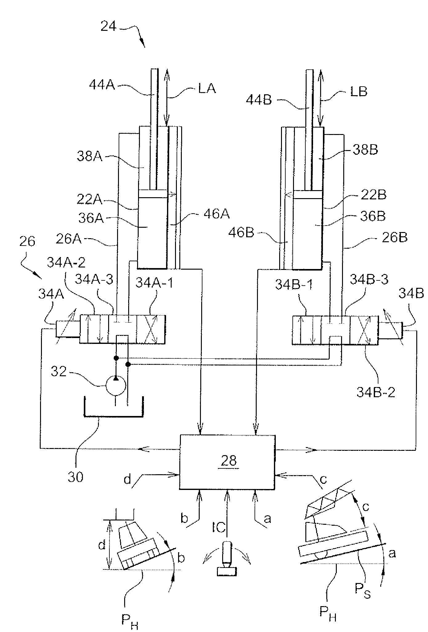
[0058]High-rise aerial apparatus 10 also includes a control device for each one of rams 22A, 22B, independently of each other. this control device 24 is illustrated in FIG. 4. As shown in FIG. 4, control device 24 includes a hydraulic circuit 26 feeding rams 22A, 22B and an electronic control unit 28. Control device 24 is supplied with hydraulic fluid—conventionally oil—from a tank 30 by means of a pump 32 for causing hydraulic fluid to circulate in hydraulic circuit 26. Hydraulic circuit 26 has two identical branches 26A, 26B each associated with one of the two rams 22A, 22B. These two branches 26A, 26B are arranged in parallel, downstream of pump 32. A solenoid valve 34A, 34B controlled by electronic control unit 28 is arranged in each of the branches 26A, 26B. In the case under discussion, the solenoid valves 34A, 34B have four ports and three operating positions.

[0059]In a first position 34A-1, 34B-1 of solenoid valves 34A, 34B, the elevation chambers 36A, 36B of rams 22A, 22B a...

second embodiment

[0101]Control device 124, in this second embodiment, further includes a fluid transfer device 140 for selectively transferring a quantity of hydraulic fluid from one of the two elevation chambers 36A, 36B to the other elevation chamber 36B, 36A. Thus, this fluid transfer device 140 operates on the principle of a pump which draws in an amount of hydraulic fluid from one elevation chamber 36A, 36B and transfers this amount of hydraulic fluid to the other elevation chamber 36B, 36A. This transfer device 140 can, as illustrated in FIG. 5, be operated by an electric motor 142 controlled by electronic control unit 128.

[0102]In a further embodiment not illustrated, the fluid transfer device can be operated by a hydraulic motor fed with hydraulic fluid from the tank via the pump. Supply of hydraulic fluid to the hydraulic motor can then be controlled by the electronic control unit, via a solenoid valve.

[0103]With this alternative embodiment of control device 124, electronic control unit 128...


PUM


Abstract

High-rise aerial apparatus mounted on a vehicle in which off-level correction is required comprises an elongate member particularly an extendable ladder or an optionally telescopic boom extending principally along one axis and able to be equipped with an aerial cage, platform or any type of similar supporting structure. The elongate member is mounted on a base, with an intermediate part interposed between the elongate member and the base, the elongate member being mounted on the intermediate part that pivots about a second axis for off-level correction of the elongate member, the intermediate part being pivotally mounted on the base via a third axis providing for elevation of a free end of the elongate member with respect to the base. Two rams for elevating and lowering the elongate member are pivotally mounted on the base and are each controlled by a controller, and can simultaneously apply off-level correction while elevating the elongate member through suitable control of the rams.

Description

FIELD OF THE INVENTION[0001]The present invention is related to a high-rise aerial apparatus and to a vehicle equipped therewith.BACKGROUND OF THE INVENTION[0002]The present invention relates to high-rise aerial apparatus and to a vehicle equipped to therewith.[0003]High-rise aerial apparatus (or high-rise aerial appliances) as used herein means, firstly, apparatus that includes a ladder. However, this expression should also be taken to mean apparatus of the furniture lift, materials lift or lifting arm type.[0004]High-rise aerial apparatus comprises an elongate member extending principally along one axis and which can typically be an extendable ladder or an optionally telescopic boom. The latter can be equipped with an aerial basket, in other words a cage, a platform or any type of similar supporting structure. The basket can optionally move along the elongate member or, alternatively, be secured to a free end of the elongate member which is designed to be elevated.[0005]In known f...

Claims


Application Information

Patent Timeline
IPC IPC(8): E06C5/04E04G1/24E06C1/38E06C5/40
CPCE06C5/40B66F11/044B60P3/14B60P3/00B66F11/00
Inventor BRUNEAU, MICHEL
Owner GIMAEX INT
Why Eureka
Try Eureka