Device and method for joining the faces of parts

a technology of parts and joints, applied in auxillary welding devices, soldering devices, ways, etc., can solve the problems of inability to produce the required joint quality, inability to rotate and inability to achieve the rotational movement of the same for friction heating of the joint area with the greatest effor

Inactive Publication Date: 2009-06-11
VOEST ALPINE SCHIENEN GMBH
View PDF29 Cites 14 Cited by
  • Summary
  • Abstract
  • Description
  • Claims
  • Application Information

AI Technical Summary

Benefits of technology

[0012]The invention provides for a device of the type mentioned at the outset with which long rods with profiled cross section, such as rails, can be joined to one another by friction welding in a rail production, whereby an axially aligned alignment and a cross-sectionally conformal, high-quality, metallic joining of the parts can be achieved.
[0013]The invention also provides for a generic method for the friction welding of rods, in particular rails, with which method an all-over, homogenous, cross-sectionally conformal, metallic joining of the ends can be achieved with a high quality of the joint area.

Problems solved by technology

Friction welded joints and devices for their production can have great importance and be very cost-effective for special materials and a joining of small or compact parts with a short time-consumption; however, with rods and the like with great longitudinal extension, a rotational movement of the same for the friction heating of the joint areas is often possible only with the greatest effort and, in many cases, only theoretically possible.
In particular, with long rods with profiled cross section, such as, e.g., rails or beams, an axially aligned joining with alignment of the cross-sectional profile through friction welding does not seem cost-effective and cannot be produced with a necessary joint quality.
However, such a rail joint, which is expensive to produce, results in respectively two weld transitions that result in an increase of potential weak points that will possibly need to be tested extensively.
Furthermore, guiding the temperature in the joint area during friction welding as well as system-dependent functional operations can be more difficult to control while maintaining quality.

Method used


Image

  • Device and method for joining the faces of parts
  • Device and method for joining the faces of parts

Examples


Embodiment Construction

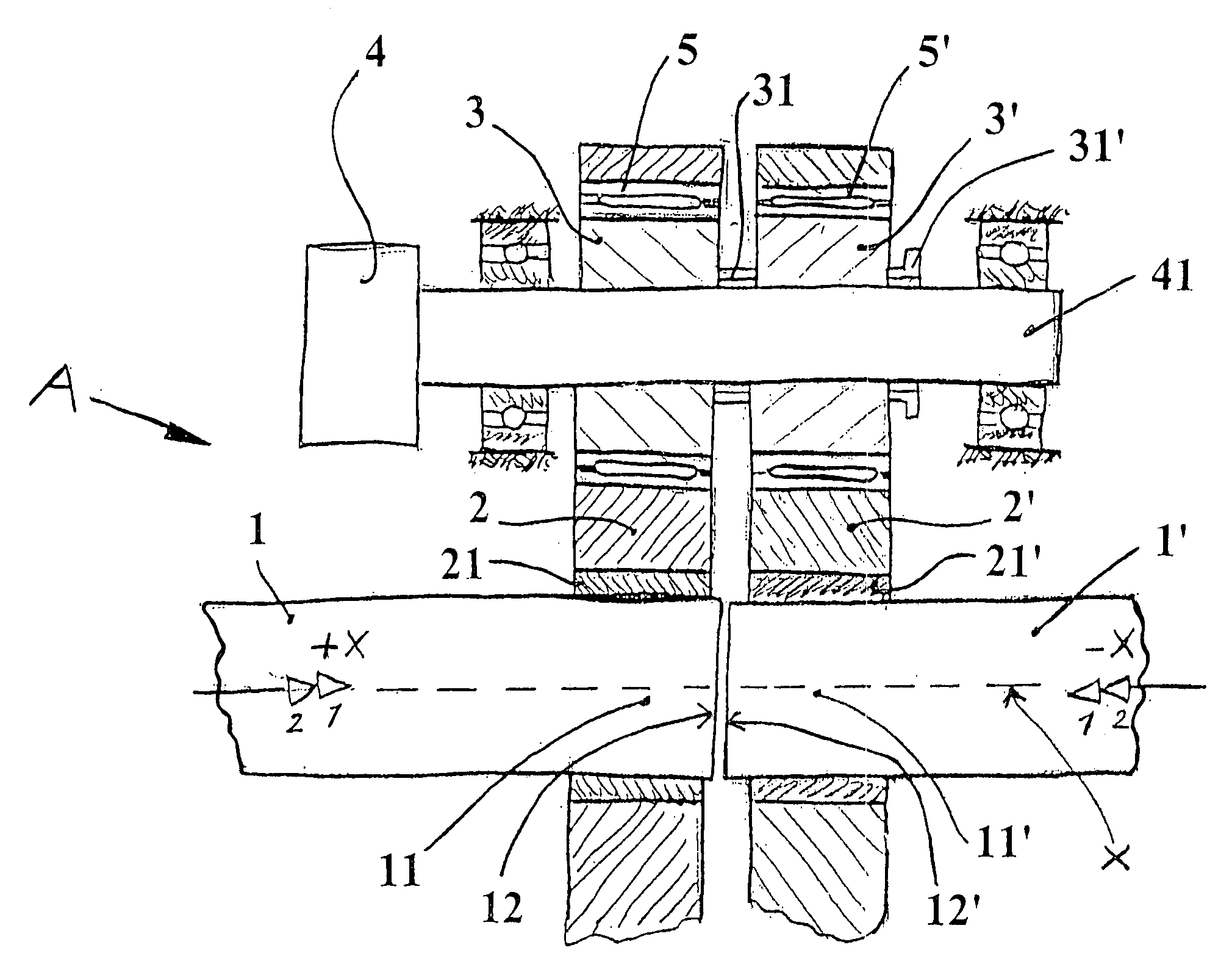
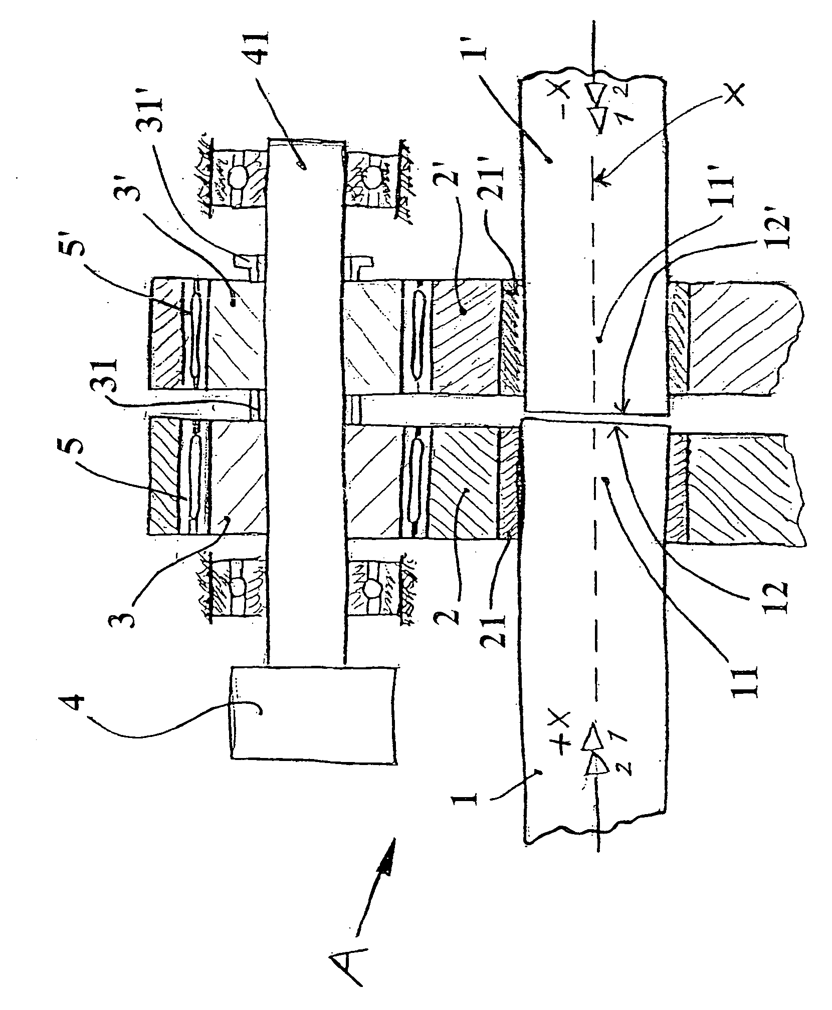
[0058]Clamping arrangements 2, 2′ are provided for parts 1, 1′ to be joined. The first and second clamping arrangements are detachably connected to the part ends 11, 11′ by clamp parts 21, 21′. The clamping arrangements 2, 2′ are operatively connected to at least respectively one adjustable eccentric arrangements 3, 3′ that can be driven by way of a shaft 41 by a motor 4 or the like, whereby the amount of eccentricity can be adjusted through a control 31, 31′ of the eccentric arrangements 3, 3′.

[0059]If the eccentric arrangements 3, 3′ are now driven in a rotary manner by a motor 4 via a shaft 41 and their eccentricity is adjusted by control means 31, 31′ in different directions, in particular in opposite directions, an uneven, in particular opposite, oscillation of the respective eccentric surfaces occurs in the direction towards the part ends 11, 11′ to be welded. However, the eccentric arrangements 3, 3′ are operatively connected to the clamping arrangements 2, 2′, if necessary v...


PUM

PropertyMeasurementUnit
movementaaaaaaaaaa
freedom of movementaaaaaaaaaa
cohesionaaaaaaaaaa

Abstract

Device for joining faces of parts having great longitudinal extension by friction welding. The device includes first and second clamping arrangements structured and arranged to position ends of the parts against one another. At least one of the first and second clamping arrangements is axially movable with respect to another of the first and second clamping arrangements. At least one of the first and second clamping arrangements is movable along a direction that is parallel to a part cross-sectional plane defined by an end face of one of the parts.

Description

CROSS-REFERENCE TO RELATED APPLICATIONS[0001]The present application is a divisional of U.S. application Ser. No. 10 / 804,132 filed Mar. 19, 2004, the disclosure of which is expressly incorporated by reference herein in its entirety. The instant application also claims priority under 35 U.S.C. §119 of Austrian Application No. A455 / 2003 filed on Mar. 21, 2003, the disclosure of which is expressly incorporated by reference herein in its entirety.BACKGROUND OF THE INVENTION[0002]1. Field of the Invention[0003]The invention relates to a device and a method for joining the faces of parts with great longitudinal extension by friction welding. In particular, the invention relates to a device and a method for the axially aligned joining of rails and the like by friction welding.[0004]2. Description of the Prior Art[0005]Joining by welding is characterized according to DIN 1910 in that the cohesion of the parts is achieved through material fusion with the use of heat and / or force. The parting...

Claims


Application Information

Patent Timeline
Patent Type & Authority Applications(United States)
IPC IPC(8): B23K20/12B23K101/26
CPCB23K20/12B23K2201/26B23K20/129B23K20/1205B23K2101/26
Inventor PFEILER, HANS
Owner VOEST ALPINE SCHIENEN GMBH
Why Eureka
Try Eureka