Spindle and flexible hinge used in ultrasonic machine

a flexible hinge and ultrasonic technology, applied in the direction of generator/motor, bathroom cover, manufacturing tools, etc., can solve the problems of complicated design of the supporting horn and the converter, and achieve the effect of reducing the design restriction on length, increasing design flexibility, and strengthening the radial rigidity of the working tool

Active Publication Date: 2009-06-11
IND TECH RES INST
View PDF8 Cites 34 Cited by
  • Summary
  • Abstract
  • Description
  • Claims
  • Application Information

AI Technical Summary

Benefits of technology

[0012]Another objective of the present invention is to provide a spindle and a flexible hinge used in an ultrasonic machine that eliminates the design restriction on length and increases design flexibility.
[0013]A further objective of the present invention is to provide a spindle and a flexible hinge used in an ultrasonic machine that strengthens radial rigidity of a working tool to facilitate machining and vibrating at the same time.

Problems solved by technology

However, the ultrasonic vibrator disclosed by US Patent Publication No. 6,762,535 does not have pre-pressure and is only connected to the supporting born functioning as a medium and not directly connected to the rotor.
That is, the design of the supporting horn is rather complicated.
However, the ultrasonic vibrator disclosed by US Patent Publication No. 7,175,506 also does not have pre-pressure and is only connected to the converter functioning as a medium and not directly connected to the rotor.
That is, the design of the converter is rather complicated.

Method used


Image

  • Spindle and flexible hinge used in ultrasonic machine
  • Spindle and flexible hinge used in ultrasonic machine
  • Spindle and flexible hinge used in ultrasonic machine

Examples


Embodiment Construction

[0022]The following illustrative embodiments are provided to illustrate the disclosure of the present invention, these and other advantages and effects can be apparent to those skilled in the art after reading the disclosure of this specification.

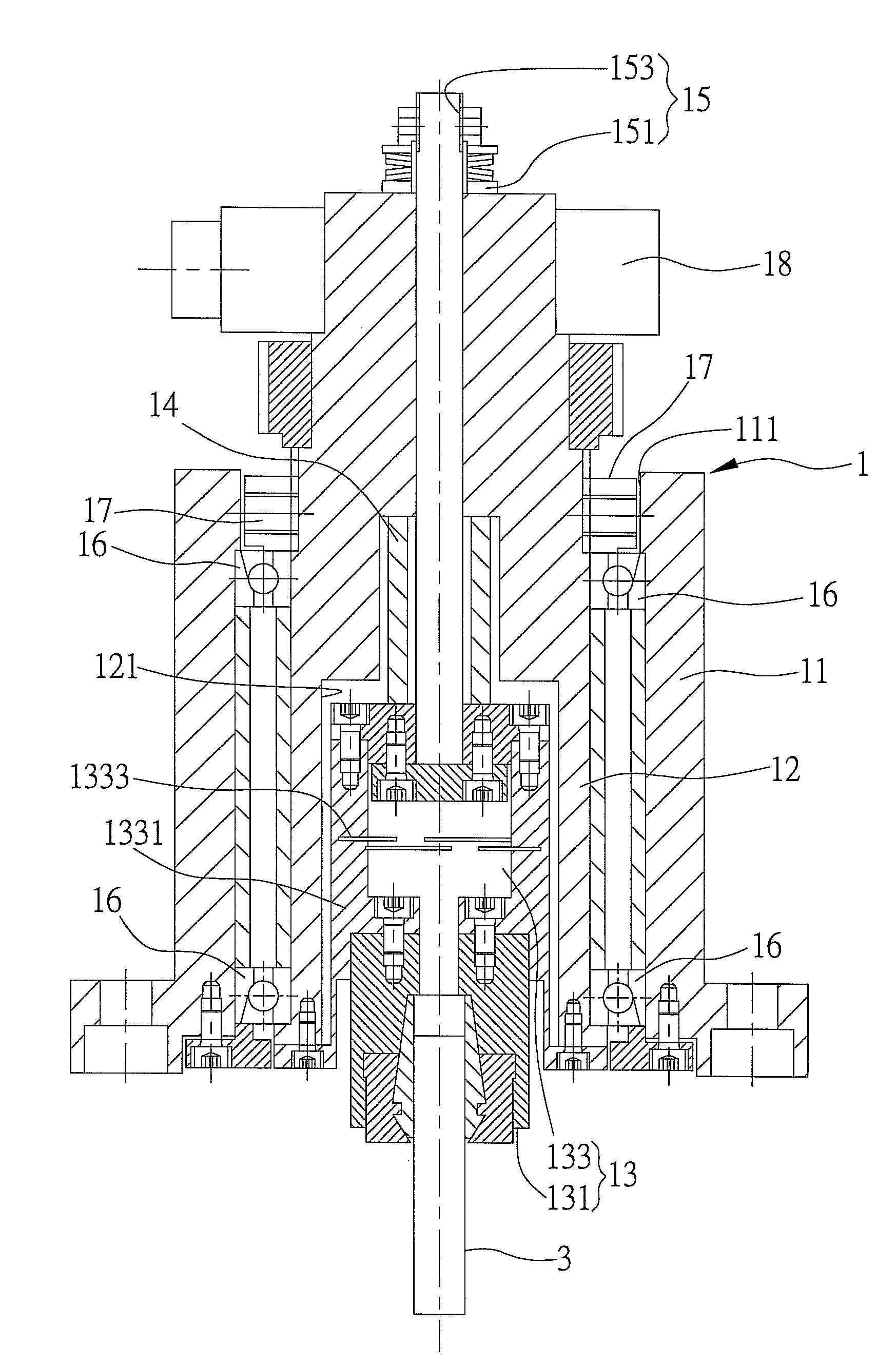
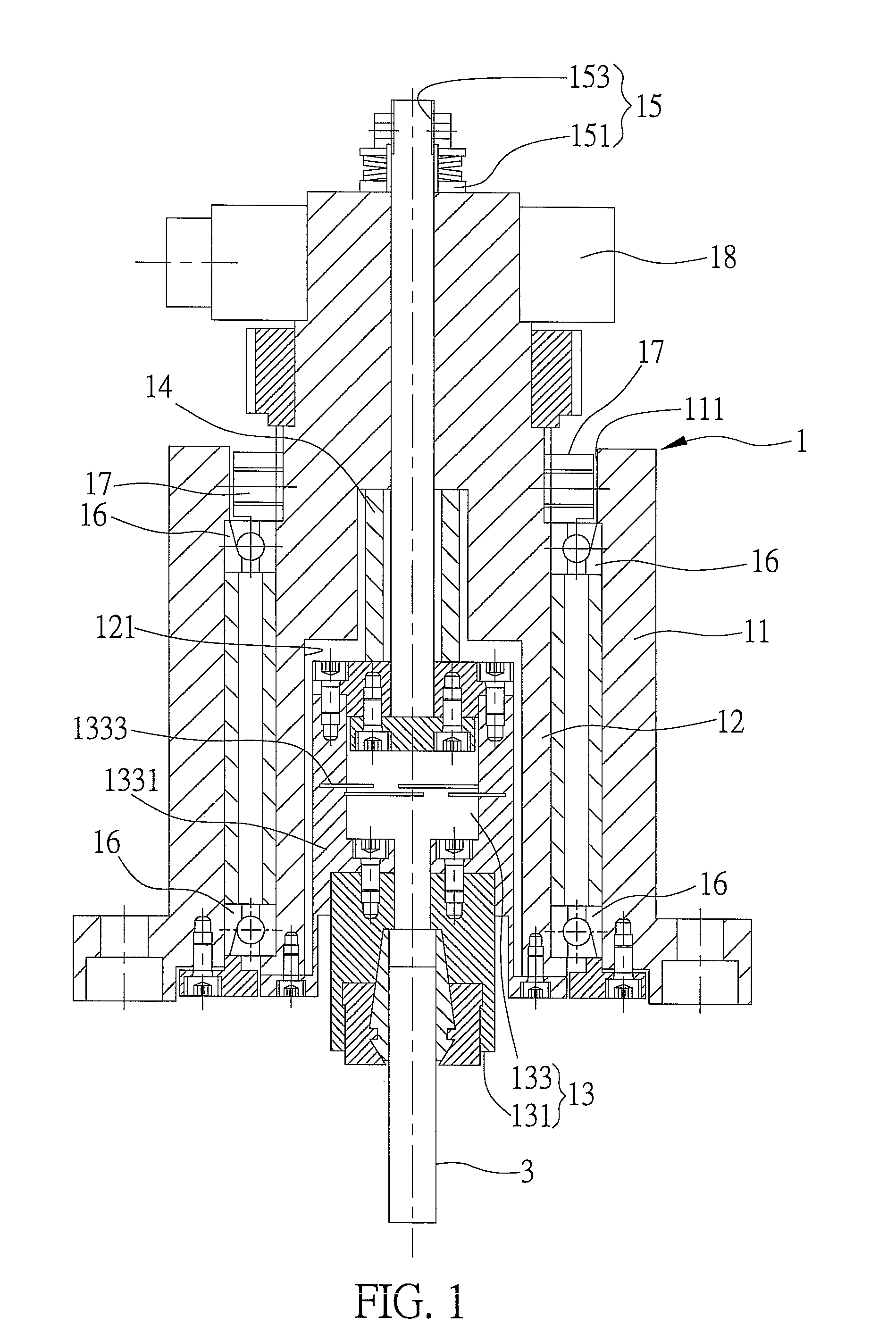
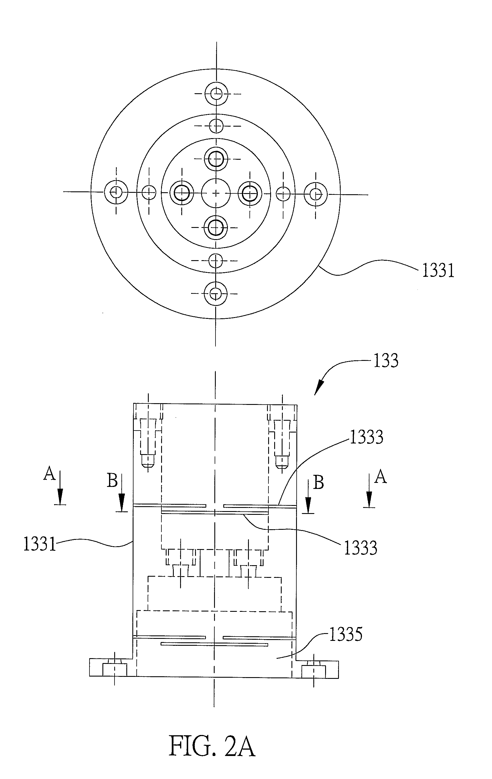
[0023]FIGS. 1 to 3B are diagrams showing a spindle and a flexible hinge according to preferred embodiments of the present invention. Therein, the spindle 1 is disposed in an ultrasonic machine for transmitting vibration to a working tool 3 of the ultrasonic machine. In the present embodiment, the working tool 3 is an end mill. To make characteristics and structures of the present invention become much more clear and for purpose of simplification, the drawings only show structures directly related to the present invention.

[0024]As shown in FIG. 1, the spindle 1 of the ultrasonic machine comprises: a main body 11; a rotor 12 disposed inside the main body 11; an elastic clamping unit 13 disposed inside the rotor 12, wherein the elastic clampin...


PUM

PropertyMeasurementUnit
flexibleaaaaaaaaaa
radial flexibleaaaaaaaaaa
piezoelectricaaaaaaaaaa

Abstract

A spindle used in an ultrasonic machine for transmitting vibration to a working tool of the ultrasonic machine is disclosed. The spindle includes a main body, a rotor disposed in the main body, an elastic clamping unit disposed in the rotor, a vibrating unit having one end thereof connected to the inner wall of the rotor while the other end connected to the elastic clamping unit, and a pre-pressure unit penetrating the rotor and one end thereof connected to the elastic clamping unit to provide the elastic clamping unit with rigidity against the rotor, thereby making the elastic clamping unit provide pre-pressure to the vibrating unit which further provides the elastic clamping unit with vibration against the rotor. The present invention further provides a flexible hinge for the spindle.

Description

BACKGROUND OF THE INVENTION[0001]1. Field of the Invention:[0002]The present invention relates generally to an ultrasonic machining technique, and more particularly to a spindle and a flexible hinge used in an ultrasonic machine.[0003]2. Description of Related Art:[0004]Since it is quite difficult to machine brittle materials such as semiconductors, ceramics, glass or hard alloys through conventional machining techniques using mechanical and thermal energies, there have been developed new machining techniques using such as electric, magnetic, optical, or chemical energies. Ultrasonic machining technique is such an assisting machining technique.[0005]Ultrasonic machining technique applies ultrasonic energy to such as cutting work, wherein vibration in an axial direction generated by an ultrasonic vibrating unit mounted to a rear end of a spindle is transmitted through the spindle and the base of a cutting tool and reaches outer periphery of the cutting tool and is converted to moveme...

Claims


Application Information

Patent Timeline
Patent Type & Authority Applications(United States)
IPC IPC(8): B24B41/04
CPCB23B31/083B23B2226/18B23B2226/45B23B2260/108B28D5/047B23C1/06B23Q1/70B24B1/04B23B2270/10
Inventor TANG, KUO-YUHUANG, CHUN-HUNGCHEN, YU-CHIEH
Owner IND TECH RES INST
Why Eureka
Try Eureka