Eureka AIR delivers breakthrough ideas for toughest innovation challenges, trusted by R&D personnel around the world.

Ink jet apparatus

Inactive Publication Date: 2009-06-11
CANON KK
View PDF3 Cites 4 Cited by
  • Summary
  • Abstract
  • Description
  • Claims
  • Application Information

AI Technical Summary

Benefits of technology

[0008]Another object of the present invention is to provide an ink jet recording apparatus, which is capable of continuously and satisfactorily wiping clean the ink ejecting surface of its recording head for a long period of time, and therefore, is capable of continuously and satisfactorily ejecting ink for a long period of time, and yet, is simple in structure. Another object of the present invention is to provide an ink jet recording apparatus, the ink ejecting performance of which remains the same whether it is used with an ink which is high in durability (fastness), or an ink which is normal in durability (fastness).
[0010]According to the present invention, it is possible to provide an ink jet recording apparatus, which is capable of maintaining the ink ejecting performance of its recording head at a satisfactorily level for a long period of time, by being capable of continuously and satisfactorily wiping clean the ink ejecting surface of its recording head for a long period of time.

Problems solved by technology

On the other hand, however, it suffers from its own problems, because it ejects ink through minute nozzles.
The adhesion of ink to the ink ejecting surface interferes with the ejection of ink from the recording head.
This cleaning method, however, is problematic in that as a blade cleaning means, such as the above described one, is repeatedly used, the contaminated ink accumulates on the blade cleaning means.
That is, the when an ink which is high in durability (fastness) is used, the porous member and / or capillary tube, with which the blade cleaning means is provided, are likely to be plugged up, and therefore, the porous member is likely to deteriorate in the ability for absorbing the contaminated ink, earlier than expected.
However, the employment of this type of method subjects the joint between the capillary tube and porous member to the load generated by the weight of the contaminated ink in the porous member.
This load interferes with the flow of the contaminated ink from the capillary tube into the porous member, making it difficult to increase the amount by which the contaminated ink can be absorbed by the porous member.
Therefore, it is difficult to continuously and satisfactorily wipe clean the ink ejecting surface of a recording head for a long time.

Method used


Image

  • Ink jet apparatus
  • Ink jet apparatus
  • Ink jet apparatus

Examples


embodiment 1

Another Embodiment of Maintenance Unit

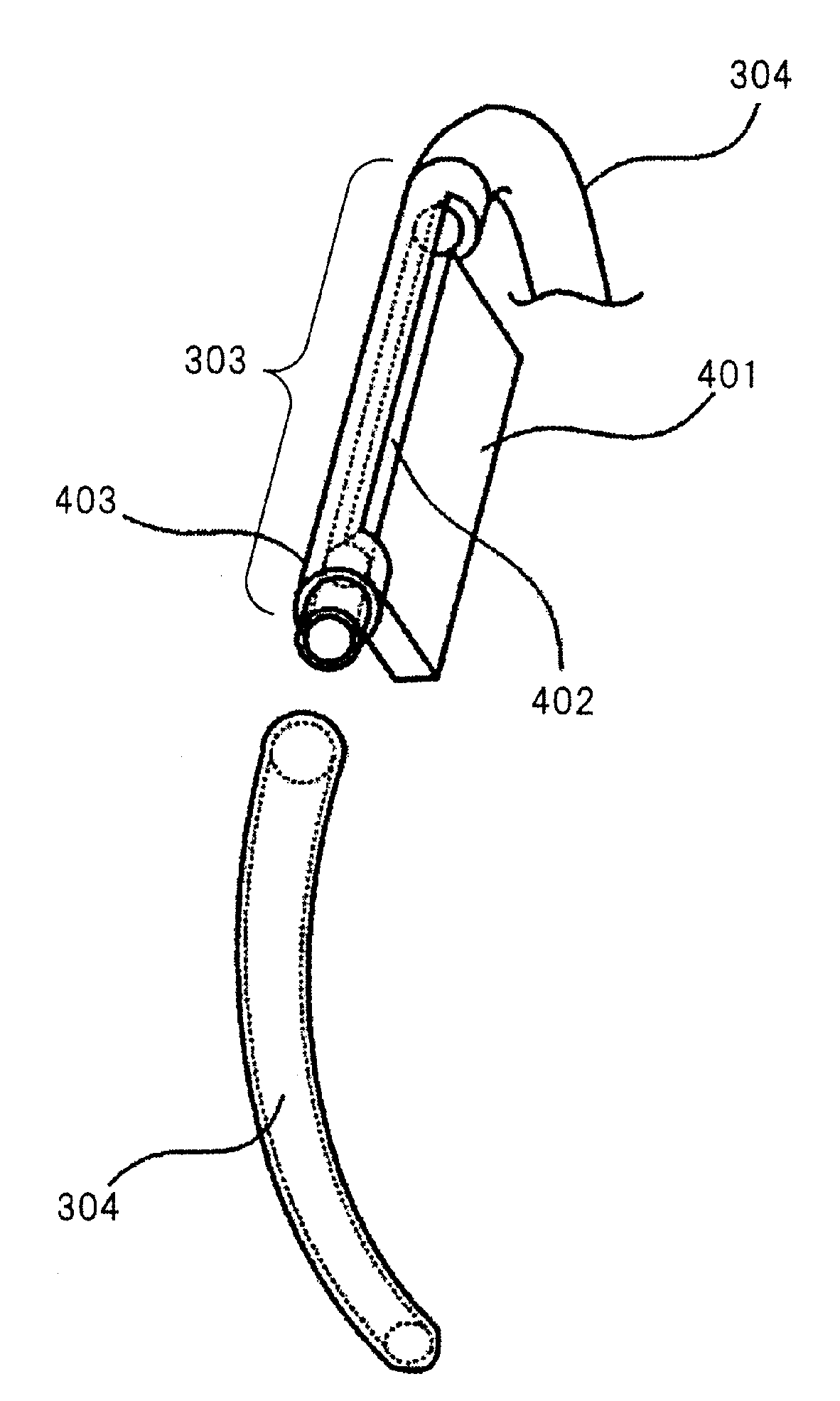
[0072]Next, another embodiment of the maintenance unit will be described. FIG. 7 is a perspective view of the maintenance unit in another embodiment of the present invention, and shows the structure of the unit. The maintenance unit in this embodiment has a pair of blades 301, a blade cleaning means 303, a cleaning liquid supplying means 305, and a waste ink absorbing means 310. These components, except for one of them, are similar in structure to the counterparts of the maintenance unit 107 shown in FIG. 3. The one component which is different from the counterpart shown in FIG. 3 is the ink guiding member for providing the maintenance unit with the ink path for guiding the contaminated ink recovered by the blade cleaning means 303, into the waste ink absorbing member 310.

[0073]In this embodiment, the maintenance unit is provided with a pair of fibrous members 311 as the members for guiding the contaminated ink into the waste ink absorbing membe...


PUM


Abstract

An ink jet recording apparatus includes a recording head having an ink ejection surface; a blade for wiping the ink ejection surface; blade cleaning means for cleaning the blade by collecting contamination liquid deposited on the blade and including at least ink; cleaning liquid supplying means for supplying, to the blade, cleaning liquid mainly comprising liquid having a volatility lower than the ink; a residual ink absorbing material provided at such a position that it is out of contact to the blade; and a discharge path for discharging the contamination ink collected by the blade cleaning means to the residual ink absorbing material.

Description

FIELD OF THE INVENTION AND RELATED ART[0001]The present invention relates to an ink jet recording apparatus which records on a recording medium by ejecting ink. In particular, it relates to an ink jet recording apparatus having a means for wiping the ink ejecting surface of its recording head.[0002]An ink jet recording apparatus forms letters, pictures, and the like images, on recording medium, by adhering to the recording medium, the ink which it ejects through the nozzles of its recording head. It is a recording apparatus of the nonimpact type, being therefore low in noise, and also, is capable of recording at a high speed as well as high level of density. On the other hand, however, it suffers from its own problems, because it ejects ink through minute nozzles. That is, while an ink jet recording apparatus is used, the ink which does not contribute to recording sometimes adheres to the ink ejecting surface of its recording head. The adhesion of ink to the ink ejecting surface int...

Claims


Application Information

Patent Timeline
IPC IPC(8): B41J2/165
CPCB41J2/16552B41J2/16541
Inventor MURAOKA, CHIAKI
Owner CANON KK
Why Eureka
Eureka Blog
Learn More