Communication terminal apparatus, base station apparatus and reception quality reporting method

a technology applied in the field of communication terminal and base station apparatus, received quality reporting method, can solve the problems of waste of uplink wireless resources, achieve the effects of preventing resource loss, reducing interference in uplink, and maintaining fair transmission allocation

Inactive Publication Date: 2009-06-11
INTERDIGITAL PATENT HLDG INC
View PDF20 Cites 41 Cited by
  • Summary
  • Abstract
  • Description
  • Claims
  • Application Information

AI Technical Summary

Benefits of technology

[0009]According to the present invention, it is possible to reduce the interference in uplink without wasting reports of received quality, perform optimal allocation by scheduling, prevent resources from being lost, and maintain fairness of transmission allocation by scheduling.

Problems solved by technology

However, when the number of subcarriers forming an OFDM signal is large, the report amount is enormous when the received quality is reported for all subcarriers, and there is a problem that uplink wireless resources are wasted.

Method used


Image

  • Communication terminal apparatus, base station apparatus and reception quality reporting method
  • Communication terminal apparatus, base station apparatus and reception quality reporting method
  • Communication terminal apparatus, base station apparatus and reception quality reporting method

Examples


embodiment 1

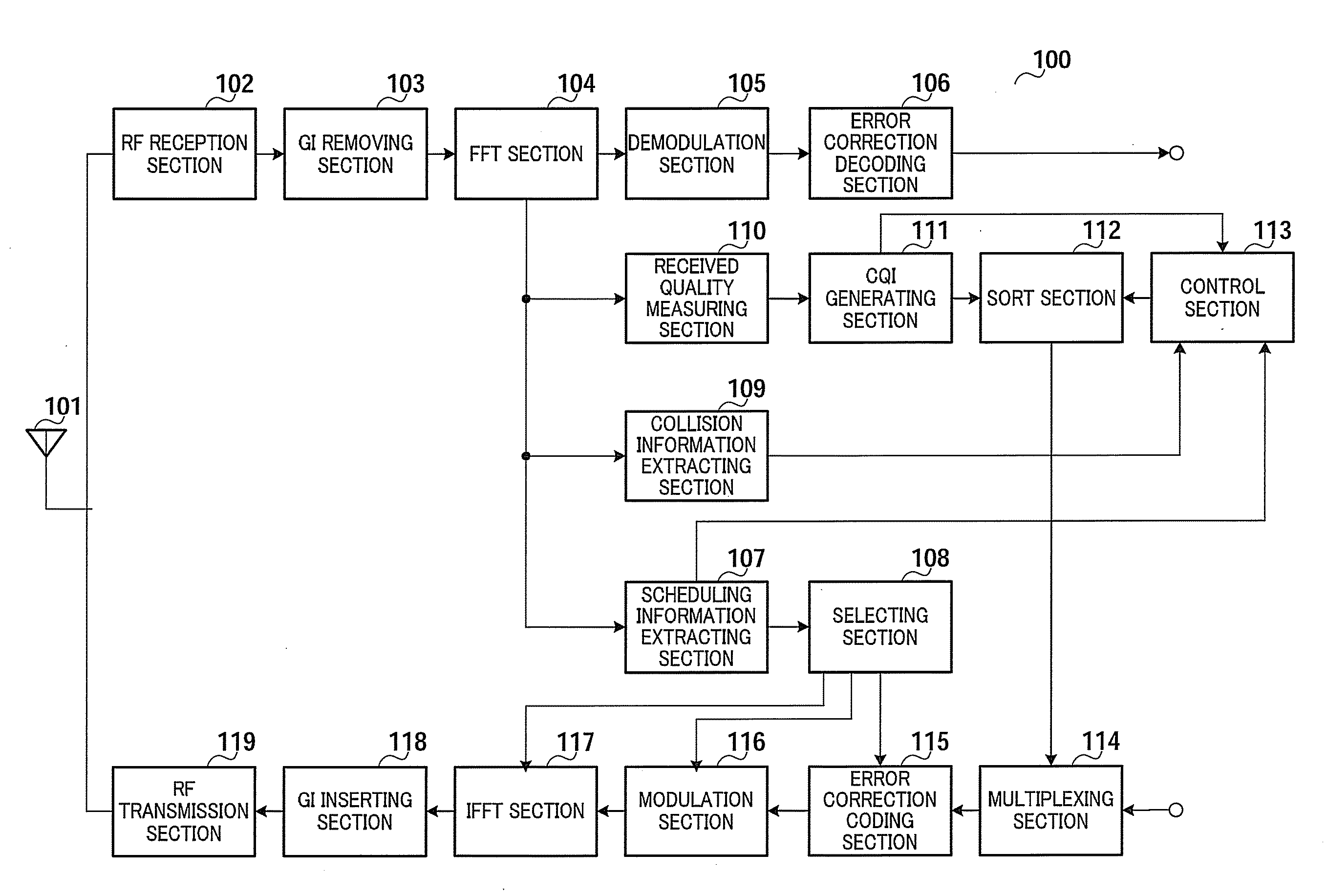
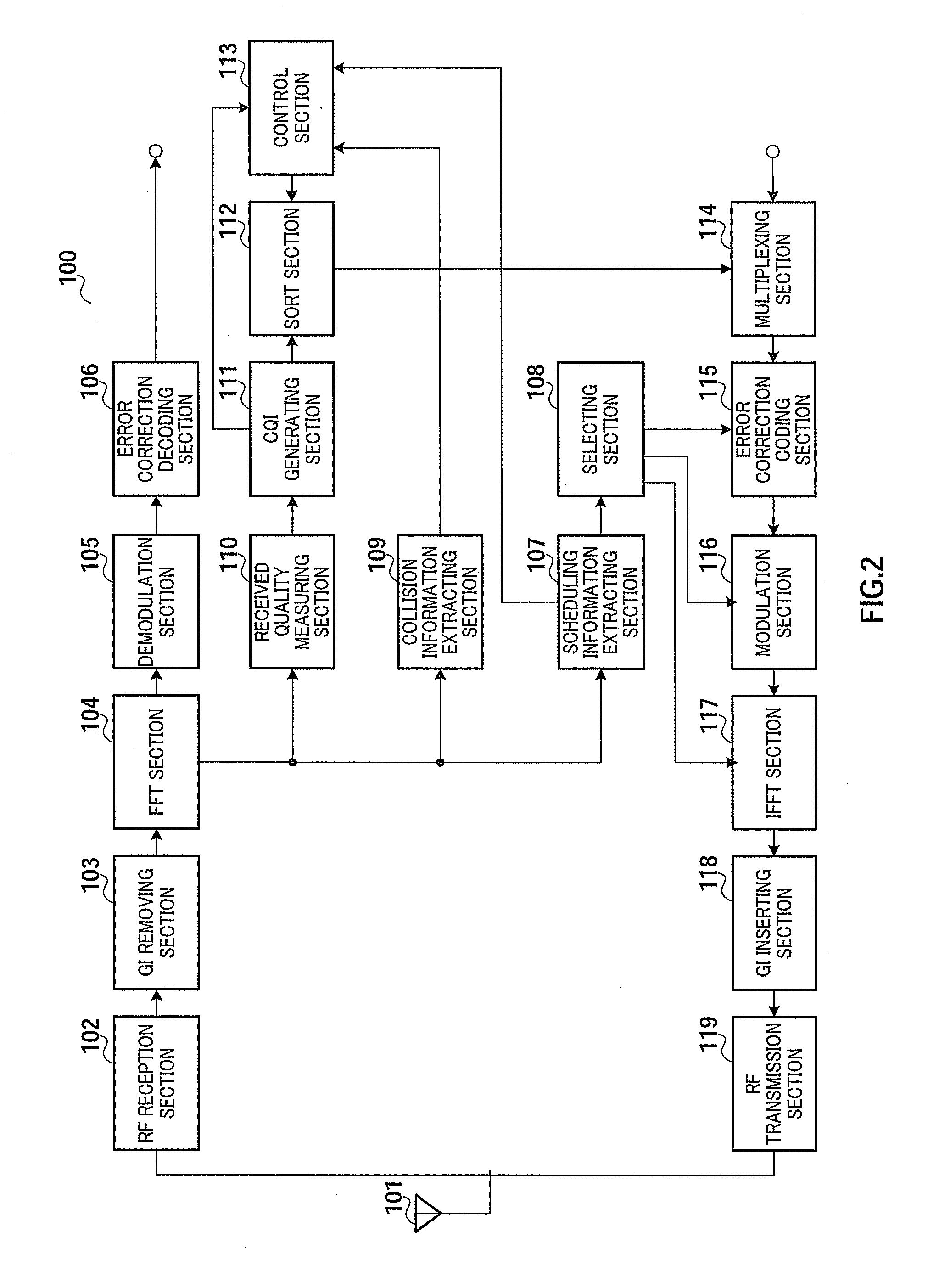
[0035]FIG. 2 is a block diagram showing the configuration of communication terminal apparatus 100 according to Embodiment 1 of the present invention.

[0036]Antenna 101 receives and outputs an OFDM signal to RF reception section 102 and transmits a transmission signal inputted from RF transmission section 119.

[0037]RF reception section 102 down-converts the received signal inputted from antenna 101 from a radio frequency to a baseband frequency and outputs the result to guard interval (hereinafter “GI”) removing section 103.

[0038]GI removing section 103 removes GIs from the received signal inputted from RF reception section 102 and outputs the result to fast Fourier transform (hereinafter “FFT”) section 104.

[0039]FFT section 104 performs FFT on the received signal inputted from GI removing section 103 and outputs the result to demodulation section 105, scheduling information extracting section 107, collision information extracting section 109 and received quality measuring section 110...

embodiment 2

[0094]FIG. 13 is a block diagram showing a configuration of comparing circuit 1200 according to Embodiment 2 of the present invention. In addition, in Embodiment 2, a configuration of a communication terminal apparatus is the same as that in FIG. 2, a configuration of a base station apparatus is the same as that in FIG. 3, and so descriptions thereof will be omitted.

[0095]In communication terminal apparatuses 100-1 and 100-2, using comparing circuit 1200 in FIG. 13, control section 113 compares a desired transmission rate by the reported CQI and a transmission rate actually assigned in base station apparatus 200. In addition, communication terminal apparatuses 100-1 and 100-2 are capable of knowing the assigned transmission rate by receiving the scheduling information. Further, as the transmission rate, for example, a bit rate is used.

[0096]As a result of comparison, control section 113 increases the number of subcarrier blocks to report the CQI when the transmission rate assigned i...

embodiment 3

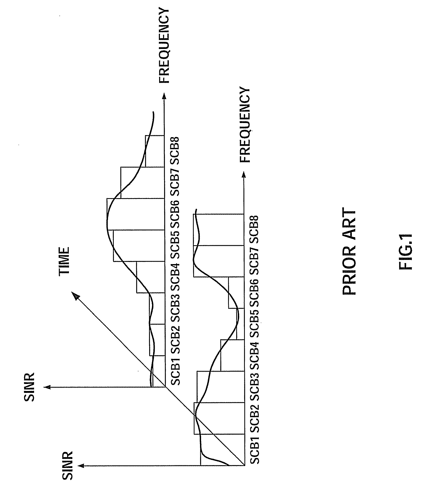
[0099]FIG. 14 shows an instantaneous allocation rate and a cumulative allocation rate measured in a communication terminal apparatus according to Embodiment 3 of the present invention. In addition, in Embodiment 3, a configuration of the communication terminal apparatus is the same as that in FIG. 2, a configuration of a base station apparatus is the same as that in FIG. 3, and so descriptions thereof will be omitted. Further, in FIG. 14, SCB is a subcarrier block.

[0100]From FIG. 14, the number of reports or report time number (A) is the number of times or time number that the communication terminal apparatus reports the CQI to the base station apparatus, and, for example, the communication terminal apparatus reports in one TTI cycle. Further, the number of report subcarrier blocks (B) designated from the base station apparatus (Node B) is the number of subcarrier blocks to report the CQI, which is designated from the base station apparatus to the communication terminal apparatus, a...


PUM


Abstract

A communication terminal apparatus that can eliminate the waste of reception quality report, suppress the interference of an upstream network, perform an optimum assignment using a scheduling, prevent the loss of resources, and ensure the fairness of transmission assignment using the scheduling. In this apparatus, a reception quality determining part (110) uses a pilot signal, which is included in a received signal, to determine the reception quality for each of subcarrier blocks. A CQI generating part (111) generates CQIs each of which is the information indicative of a result of the determination by the reception quality determining part (110). A sorting part (112) sorts the CQIs in descending or ascending order of the reception quality. A control part (113) instructs, based on information about the number of subcarrier blocks in which the CQIs have been transmitted, collision information and scheduling information, the sorting part (112) with respect to the number of subcarrier blocks in which the CQIs are outputted.

Description

TECHNICAL FIELD[0001]The present invention relates to a communication terminal apparatus, base station apparatus and received quality reporting method. More particularly, the present invention relates to a communication terminal apparatus, base station apparatus and received quality reporting method for reporting received quality in uplink in a multicarrier transmission scheme.BACKGROUND ART[0002]In OFDM (Orthogonal Frequency Division Multiplex) transmission, as shown in FIG. 1, there are cases where communication quality of each subcarrier block (SCB1 to SCB8) is different from one another due to frequency selective fading. Further, in downlink OFDM transmission, channel states vary for each communication terminal apparatus (UE), and so, by making each communication terminal apparatus report the received quality to the base station apparatus (Node B), the base station apparatus can select per communication terminal apparatus only subcarriers having good received quality and allocat...

Claims


Application Information

Patent Timeline
Patent Type & Authority Applications(United States)
IPC IPC(8): H04L27/28H04W24/10H04W72/04H04W72/12
CPCH04L1/0026H04L1/0029H04L1/0027
Inventor DUAN, JINSONGSUMASU, ATSUSHI
Owner INTERDIGITAL PATENT HLDG INC
Why Eureka
Try Eureka