
Fixing device and image-forming apparatus comprising the same

a technology of fixing device and image forming apparatus, which is applied in the direction of electrographic process apparatus, instruments, optics, etc., can solve the problems of removing the recording medium of the user, unable to operate the lever, and unable to remove the recording medium, etc., to achieve the effect of removing residual toner

Inactive Publication Date: 2009-06-11
RICOH KK
View PDF11 Cites 112 Cited by
  • Summary
  • Abstract
  • Description
  • Claims
  • Application Information

AI Technical Summary

Benefits of technology

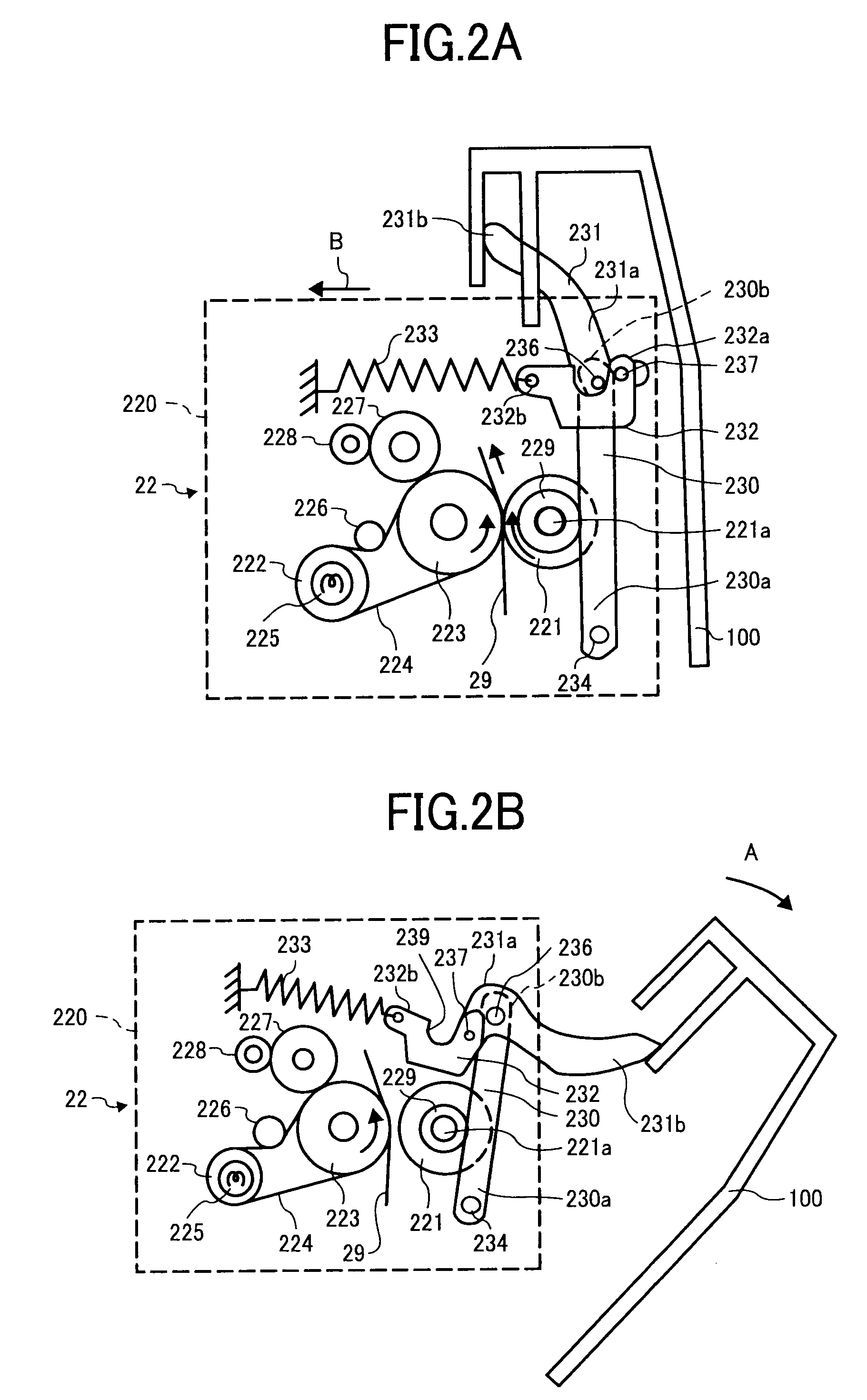
The present invention provides a fixing device and image-forming apparatus that provide good glossiness and paper adaptability while also being easy to operate and durable. The fixing device uses a pair of opposing fixing members to grip a recording medium and fix a toner image onto it by applying heat and / or pressure. The device includes a pressure-applying lever, a pressure-releasing lever, a locking member, and an elastic member that pulls the locking member in a locking direction. The rotation of the pressure-releasing lever changes the position of the locking member, allowing for switching between a pressure-applying position and a pressure-releasing position. The elastic member engages with the locking member and pulls it in the locking direction. The image-forming apparatus includes an image carrier, a charging device, an exposure device, a developing device, a cleaning device, a transfer device, and a fixing device. The fixing device is easy to operate and provides good glossiness and paper adaptability.

Problems solved by technology

However, when a paper jam creates a state in which the recording medium becomes stuck in the fixing nip of this fixing device and the apparatus stops, jam processing, in which the user removes this recording medium, is extremely difficult due to the fact that the recording medium is stuck in a state in which pressure is being applied to the fixing nip.
The problems with the manual method are the complicated nature of the lever operation and forgetting to operate the lever.
The above-mentioned Prior Art 1 comprises a cam device for automatically releasing the contact pressure of the fixing nip, but this requires the disposition of a new drive mechanism such as a dedicated motor, increasing the weight and cost of the device.
On the other hand, since the speed at which the paper passes through has become faster, the heat applied to the recording medium at fixing is no longer sufficient, making it difficult to achieve satisfactory fixing performance.
The problem with this is that the actuating force on the conventional manual release lever becomes too great, making it difficult for the user to operate.
Further, in the case of a configuration which causes a cam attached to a release lever to act on a direct-pressure-applying lever to release the pressure-applying state of the fixing members as disclosed in the above-mentioned Prior Art 2, the problem is that strengthening the pressure-applying force increases the frictional force between the cam and the direct-pressure-applying lever, thereby lowering the sliding performance of the sliding contact surface, and also increasing the wear on the sliding contact surface.
Even when the release of the pressure-applying state of the fixing members is linked to the opening and closing of a cover as disclosed in the above-mentioned Prior Art 3, the problem is that strengthening the pressure-applying force increases the frictional force of the contact surfaces of the release lever and opening-and-closing cover, lowering the sliding performance of the sliding contact surfaces and increasing the mutual wear on the sliding contact surfaces.
However, in recent years, the glossiness required for an output image has come to differ by the application and type of paper of the recording medium, and fixability for a variety of recording media is required.

Method used


Image

  • Fixing device and image-forming apparatus comprising the same
  • Fixing device and image-forming apparatus comprising the same
  • Fixing device and image-forming apparatus comprising the same

Examples


Embodiment Construction

(s)

[0035]The present invention will be explained hereinbelow by referring to the figures.

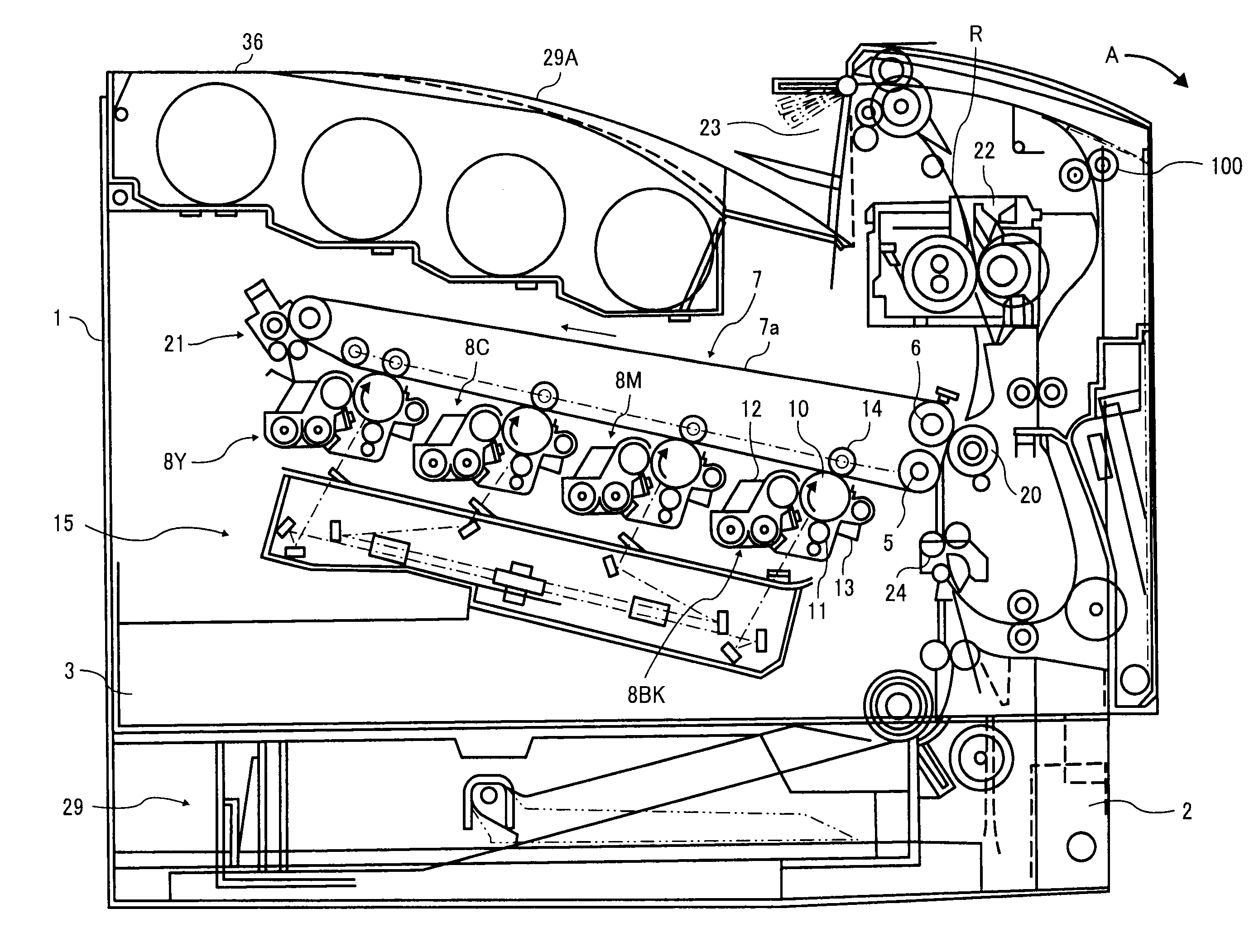
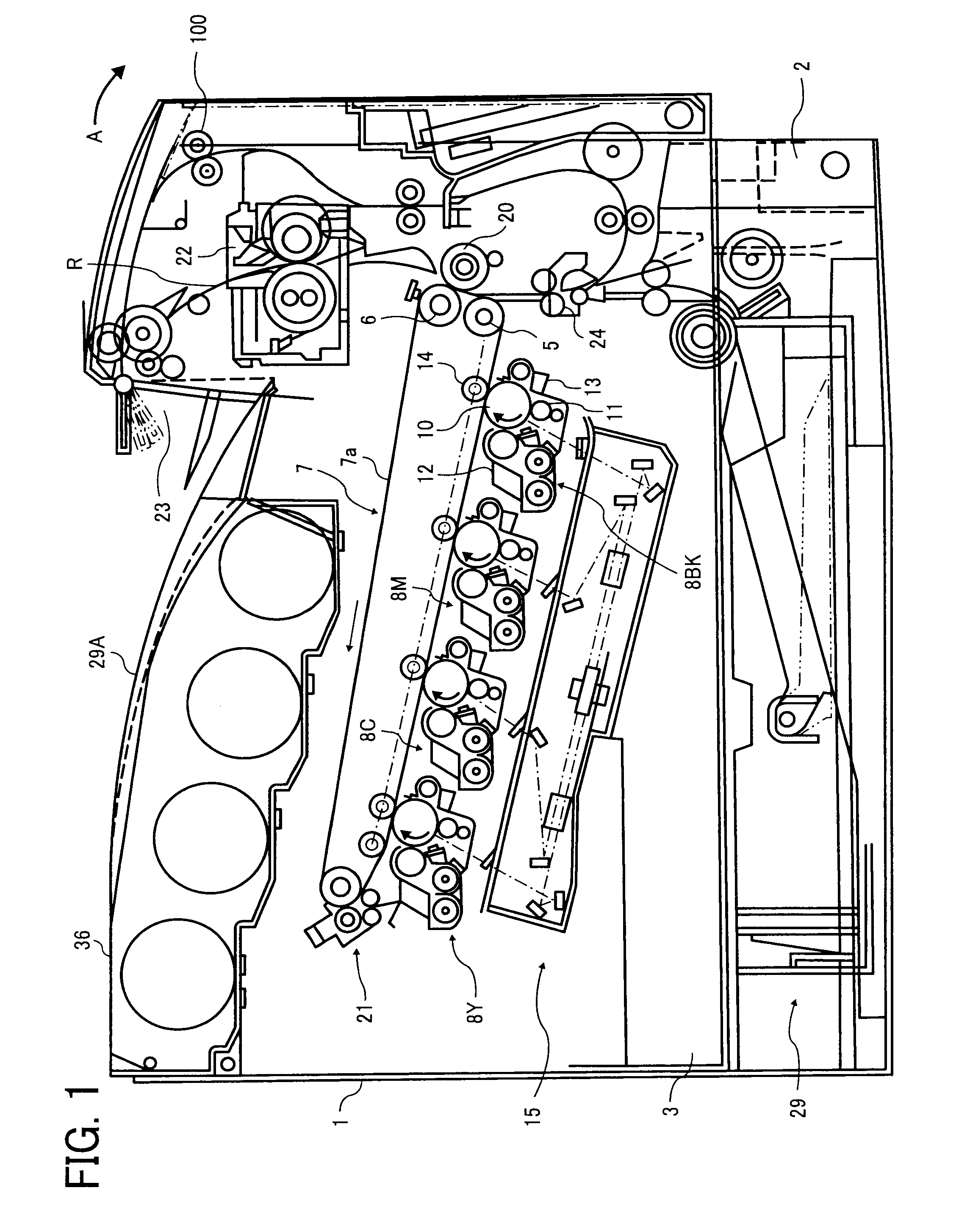
[0036]FIG. 1 shows the approximate configuration of a color printer (hereinafter called the “printer”), in which an image-forming apparatus of the present invention can be used in tandem with a digital photography system to form a full-color image. The image-forming apparatus is not limited to the printer shown in FIG. 1, but rather can also be a copier, a facsimile machine or the like.

[0037]Referring to FIG. 1 of the drawings, the basic configuration of this printer and the operation thereof will be explained, and thereafter, the configuration and operation peculiar to the present invention will be explained.

[0038]This printer constitutes a configuration in which a paper feeding cassette 2, in which paper 29 that serves as the recording medium is stored, is arranged below the image-forming apparatus main unit 1, which constitutes the basis of the printer, and an image-forming part 3 is arranged...


PUM


Abstract

A fixing device and image-forming apparatus, which provide required glossiness and paper adaptability, and, in addition, feature good operability and excellent durability while achieving optimal pressure-applying force for a variety of requirements, having: a pressure-applying lever; a pressure-releasing lever; a locking member, the one end of which is rotationally attached to the pressure-releasing lever; and an elastic member, which pulls the locking member in a locking direction. The configuration is such that the rotation of the pressure-releasing lever displaces the location of the locking member, thereby enabling switching between a pressure-applying position, in which a fixing member presses against another fixing member, and a pressure-releasing position, in which the one fixing member moves away from the other fixing member, and in the pressure-applying position, the pressure-applying lever and the locking member, which are fastened together at one end of the pressure-applying lever opposite a rotation central shaft, are pulled in a locking direction by the elastic member, and the gripping pressure on a piece of paper is varied by the pair of fixing members.

Description

BACKGROUND OF THE INVENTION[0001]1. Field of the Invention[0002]The present invention relates to a fixing device, which grips a recording medium on which a toner image has been formed between a pair of mutually opposed fixing members, and fixes the toner image to the recording medium by applying heat and / or pressure, and an image-forming apparatus comprising this fixing device.[0003]2. Description of the Related Art[0004]In an image-forming apparatus that utilizes a digital photography system, an electrostatic latent image is formed on the surface of a photosensitive drum, which is one example of an image carrier, this electrostatic latent image is made into a visible image by using a toner or the like, which is a developer, to develop the electrostatic image on the photosensitive drum, the developed image is transferred to a transfer material by a transfer device, the transfer material carries the image, and a fixing device fixes the toner image onto the transfer material using pre...

Claims


Application Information

Patent Timeline
Patent Type & Authority Applications(United States)
IPC IPC(8): G03G15/20
CPCG03G15/2035
Inventor YOSHINAGA, HIROSHIEHARA, MASANAOSHINSHI, AKIRAIWAYA, NAOKIYAMAGUCHI, YOSHIKI
Owner RICOH KK
Learn More