Flexible stent

Inactive Publication Date: 2009-06-11
NUMED INC
View PDF7 Cites 32 Cited by
  • Summary
  • Abstract
  • Description
  • Claims
  • Application Information

AI Technical Summary

Benefits of technology

[0006]It is a further object to provide greater flexibility to an intravascular stent without sacrificing the stents overall strength.
[0007]Another object of the present invention is to provide a flexible stent that does not become foreshortened as it is expanded.
[0008]Yet another object of the present invention is to provide a stent that can be further expanded beyond its initi

Problems solved by technology

This renders the stent less than suitable for use in association with a child who over time can grow to a size such that the stent is no longer reliable.
This, in turn, makes positioning of the stent within a body cavity somewhat difficult.
Lastly, wire wound st

Method used


Image

  • Flexible stent
  • Flexible stent
  • Flexible stent

Examples


Embodiment Construction

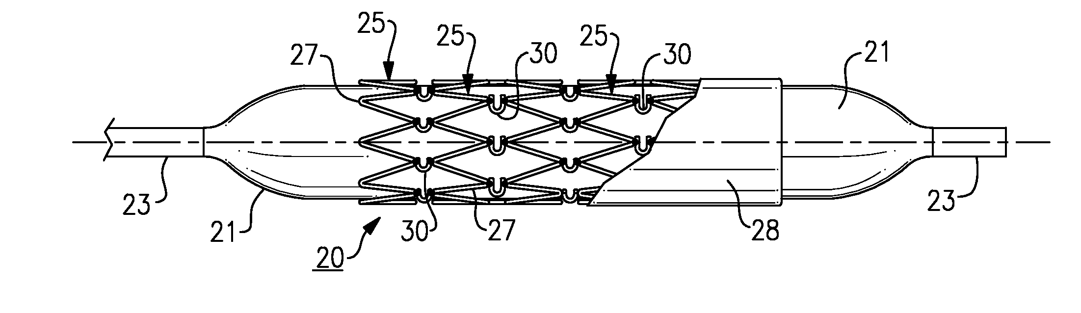
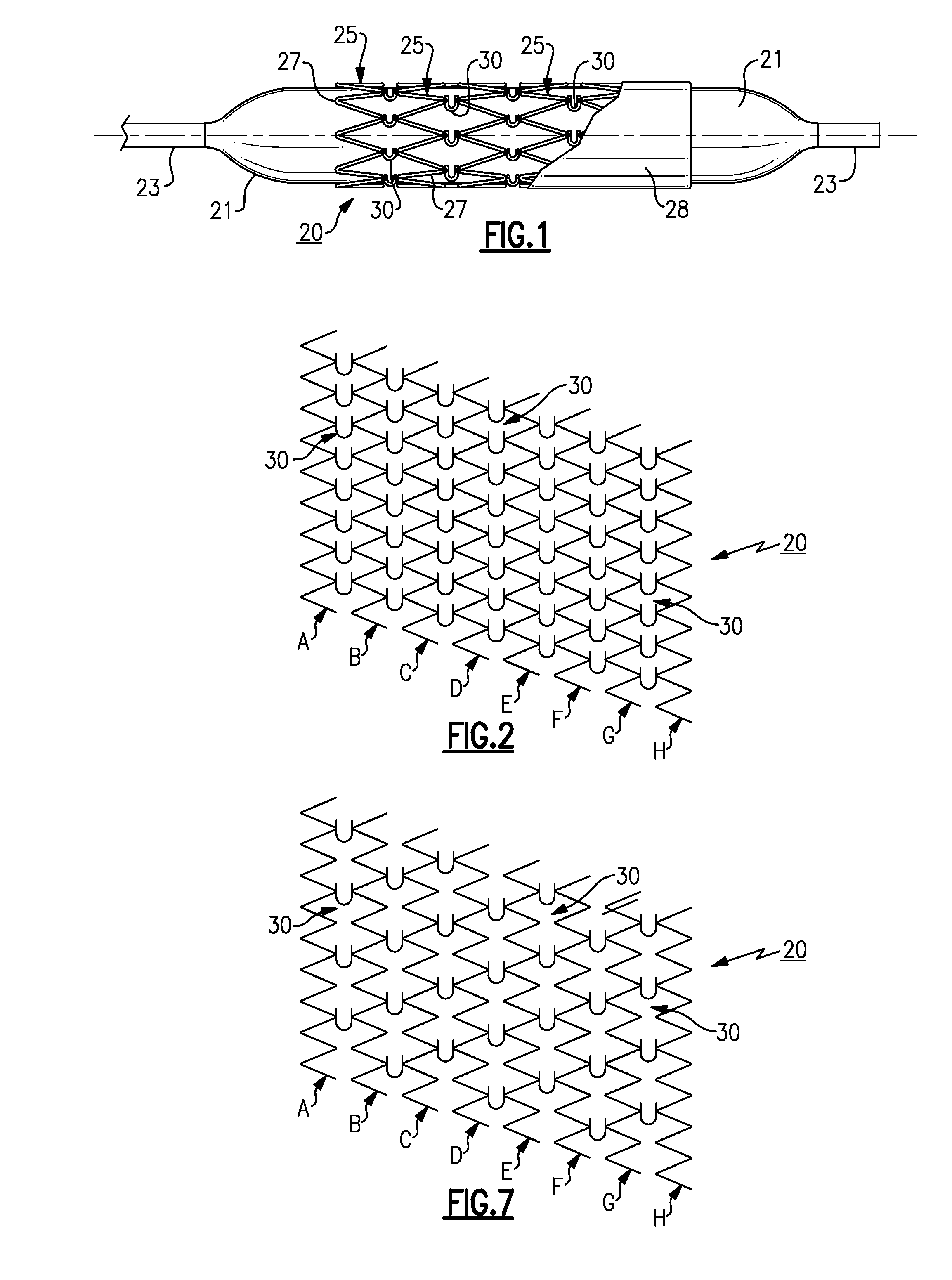
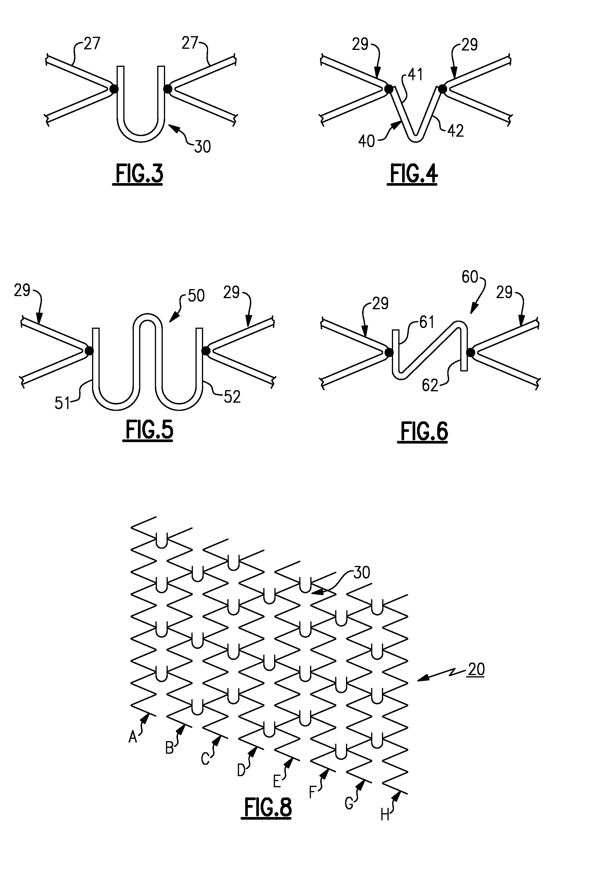
[0018]The present stent is shown in FIG. 1 in an inflated condition. The stent includes a number of circular wire wound sections 25-25 that are coaxially aligned along a center axis 26 to establish a cylinder of given length. Each section, in turn, contains a single strand of wire that is in the form of a sinusoid that passes back and forth along the circumference of the section. Each wire sinusoid has a series of uniformly spaced bends, the tips 27 of which describe the opposed side boundaries of the sections. In assembly, the sections are aligned so that tip running along one side of a section are located adjacent to and in close proximity with tips contained in a neighboring section. Selected ones of the adjacent tip pairs are connected together by a single wire hinge 30. Preferably at least two hinges are used to connect each of the sections to its neighbor to hold the sections in a cylindrical alignment. The stent may be covered with a bio-compatible sleeve 28 fabricated of Tef...


PUM


Abstract

This invention involves a radially expandable stent that has wire wound circular sections that are cojoined to create a cylinder by a series of single strand wire hinges. The hinges are situated to provide the stent created by the expanded sections with enhanced flexibility without sacrificing the overall support strength of the stent.

Description

FIELD OF THE INVENTION[0001]This invention relates to a percutaneously implantable stent having improved flexibility that allows the stent to flex in a number of directions without the loss of the strength.BACKGROUND OF THE INVENTION[0002]Intervascular stents that are capable of being percutaneously implanted via a blood vessel are typically carried into the treatment site upon a balloon catheter with the stent in a collapsed condition upon the balloon. Once the stent is properly located within the site, the balloon is inflated to expand the stent into an operable position. Once brought into the operative position the stent locks in place and little more can be done to change the rigid expanded posture. This renders the stent less than suitable for use in association with a child who over time can grow to a size such that the stent is no longer reliable.[0003]It should be further noted, that the circular sections of wire wound stents found in the prior art are generally held togethe...

Claims


Application Information

Patent Timeline
IPC IPC(8): A61F2/86A61F2/90
CPCA61F2/90A61F2/915A61F2002/30451A61F2230/0054A61F2002/91558A61F2220/0058A61F2250/0018A61F2002/91533
Inventor TOWER, ALLEN
Owner NUMED INC
Why Eureka
Try Eureka