Effective driveline vibration detection algorithm in transmission tcc slip control

Active Publication Date: 2009-06-11
GM GLOBAL TECH OPERATIONS LLC
View PDF14 Cites 17 Cited by
  • Summary
  • Abstract
  • Description
  • Claims
  • Application Information

AI Technical Summary

Problems solved by technology

Because large slips between the engine output and the transmission input significantly affect the fuel economy of the vehicle, some vehicles employ a torque converter clutch (TCC) for controlling or reducing the slip between the engine and

Method used


Image

  • Effective driveline vibration detection algorithm in transmission tcc slip control
  • Effective driveline vibration detection algorithm in transmission tcc slip control
  • Effective driveline vibration detection algorithm in transmission tcc slip control

Examples


Embodiment Construction

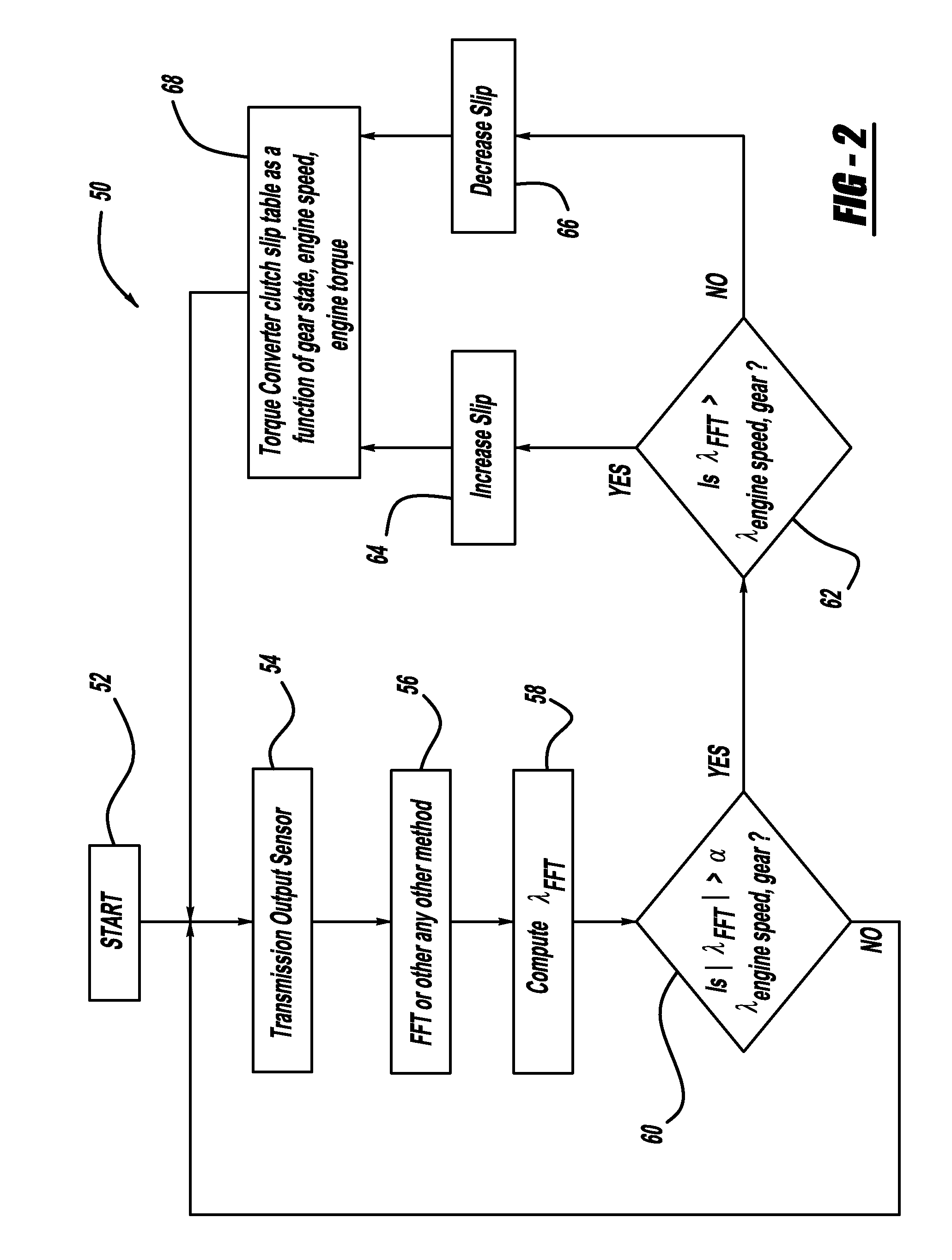
[0015]The following discussion of the embodiments of the invention directed to a method for adjusting a slip for a torque converter between a vehicle engine and transmission is merely exemplary in nature, and is in no way intended to limit the invention or its applications or uses.

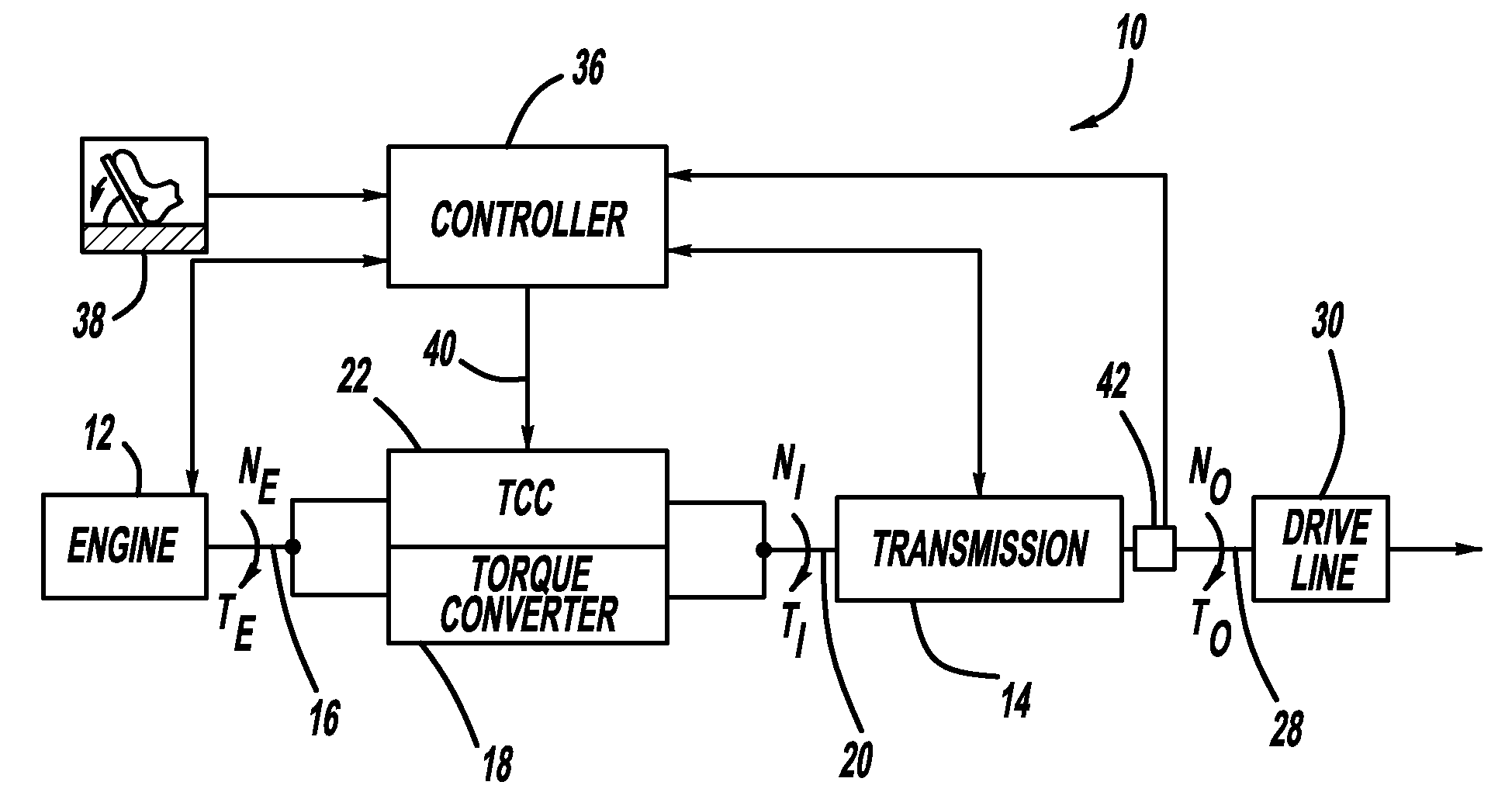
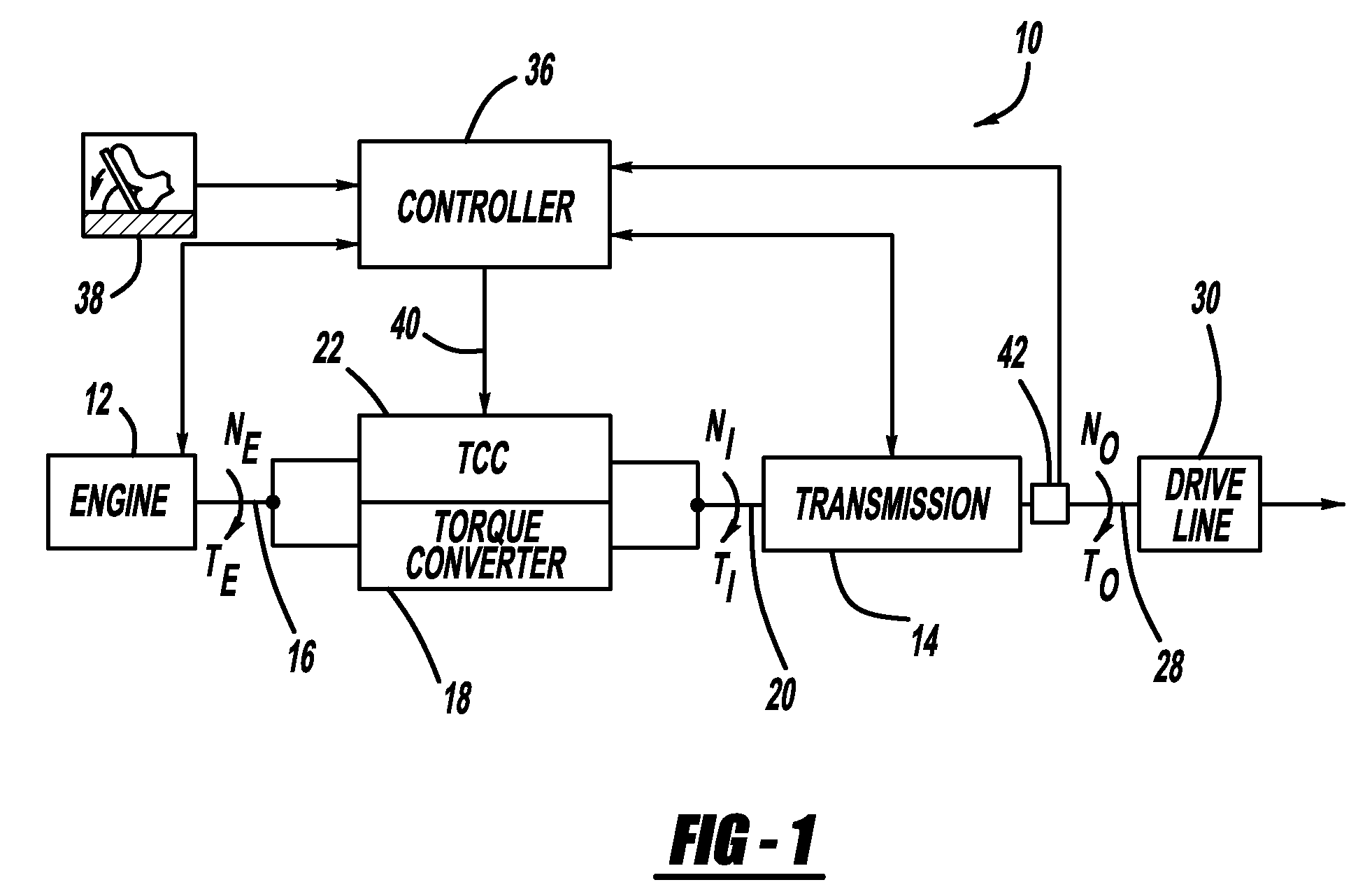
[0016]FIG. 1 is a block diagram of various power-train components of a vehicle 10. The power-train components include an engine 12 and a transmission 14. An output shaft of the engine 12, represented by line 16, is coupled to one end of a torque converter 18, and an input shaft of the transmission 16, represented by line 20, is coupled to an opposite end of the torque converter 18. As discussed above, the torque converter 18 transfers rotational energy from the engine 12 to the transmission 14 using hydraulic fluid so that the engine 12 can be disengaged from the transmission 14 when necessary. A TCC 22 sets a torque converter slip in the torque converter 18 between the engine 12 and the transmission 14, a...


PUM


Abstract

A method for adjusting the slip of a torque converter for a plurality of selected engine speeds, transmission gears and engine torque. A sensor is used to determine vibrations transmitted through the torque converter to the driveline of the vehicle. The sensor signal is sent to a controller where it is converted to the frequency domain. If the amplitude of the frequency signal exceeds a threshold, then the algorithm increases/decreases the converter slip until the driveline vibrations equal a threshold.

Description

CROSS-REFERENCE TO RELATED APPLICATIONS[0001]This application claims priority to U.S. Provisional Patent Application Ser. No. 61 / 012,194, filed Dec. 7, 2007, titled “Aggressive Torque Converter Clutch Slip Control Design through Driveline Torsional Velocity Measurements.”BACKGROUND OF THE INVENTION[0002]1. Field of the Invention[0003]This invention relates generally to a system and method for setting the slip in a torque converter of a vehicle and, more particularly, to a system and method for providing a minimum torque converter slip in response to changes in engine speed and transmission gears so as to minimize vehicle driveline vibrations and provide good fuel economy.[0004]2. Discussion of the Related Art[0005]Internal combustion engine vehicles that employ automatic transmissions typically include a torque converter positioned between the engine and the transmission of the vehicle. A torque converter is a fluid coupling device typically including an impeller coupled to an outpu...

Claims


Application Information

Patent Timeline
IPC IPC(8): G06F7/00
CPCY10T477/755G01M13/022
Inventor SAMIE, FARZADLEE, CHUNHAO J.OTANEZ, PAUL G.
Owner GM GLOBAL TECH OPERATIONS LLC
Why Eureka
Try Eureka