Turbulence conditioner for transit time ultrasonic flow meters and method

Active Publication Date: 2009-06-18
SENSIA LLC
View PDF10 Cites 30 Cited by
  • Summary
  • Abstract
  • Description
  • Claims
  • Application Information

AI Technical Summary

Benefits of technology

[0029]The present invention pertains to a method for determining fluid flow in a pipe. The method comprises the steps of flowing fluid through a turbulence conditioner disposed in the pipe having openings where the pitch between openings is made a function of an effective diameter of an aperture of an ultrasonic flowmeter which communicates with the interior of the pipe through the aperture. There is the step of measuring the flow with the meter.
[0030]The present invention pertains to a method for producing a turbulence conditioner for use with an ultrasonic flow meter in a pipe. The method comprises the steps of identifying an effective diameter of an aperture in the pipe through which the flowmeter communicates with the interior of the pipe. There is the step of determining a pitch between holes

Problems solved by technology

However, characteristics inherent in the nature of their measurements present difficulties when these meters are applied to custody transfer measurements of petroleum products.
Meeting these requirements is not straightforward.
This, then, is the problem.
Turbulence, such as normally encountered in petroleum product pipelines, adversely affects the repeatability of the meter factors for transit time ultrasonic flowmeters, as measured in short duration pr

Method used


Image

  • Turbulence conditioner for transit time ultrasonic flow meters and method
  • Turbulence conditioner for transit time ultrasonic flow meters and method
  • Turbulence conditioner for transit time ultrasonic flow meters and method

Examples


Embodiment Construction

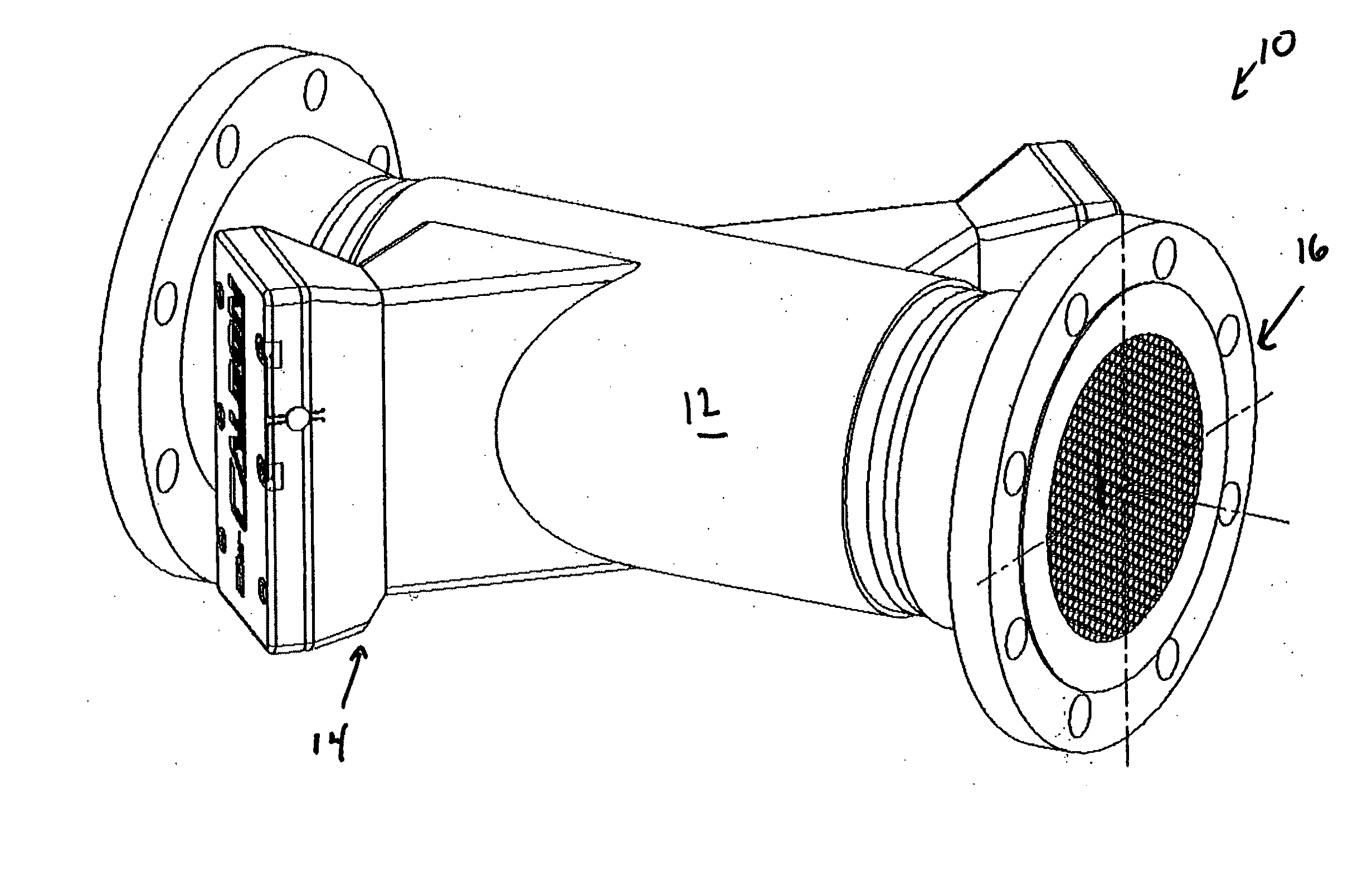
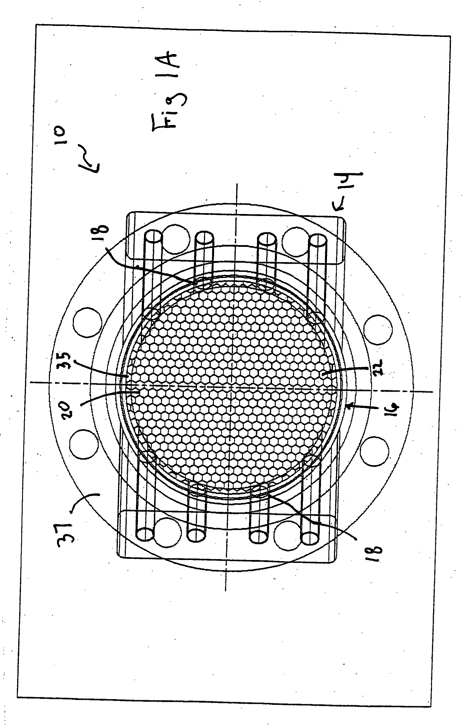
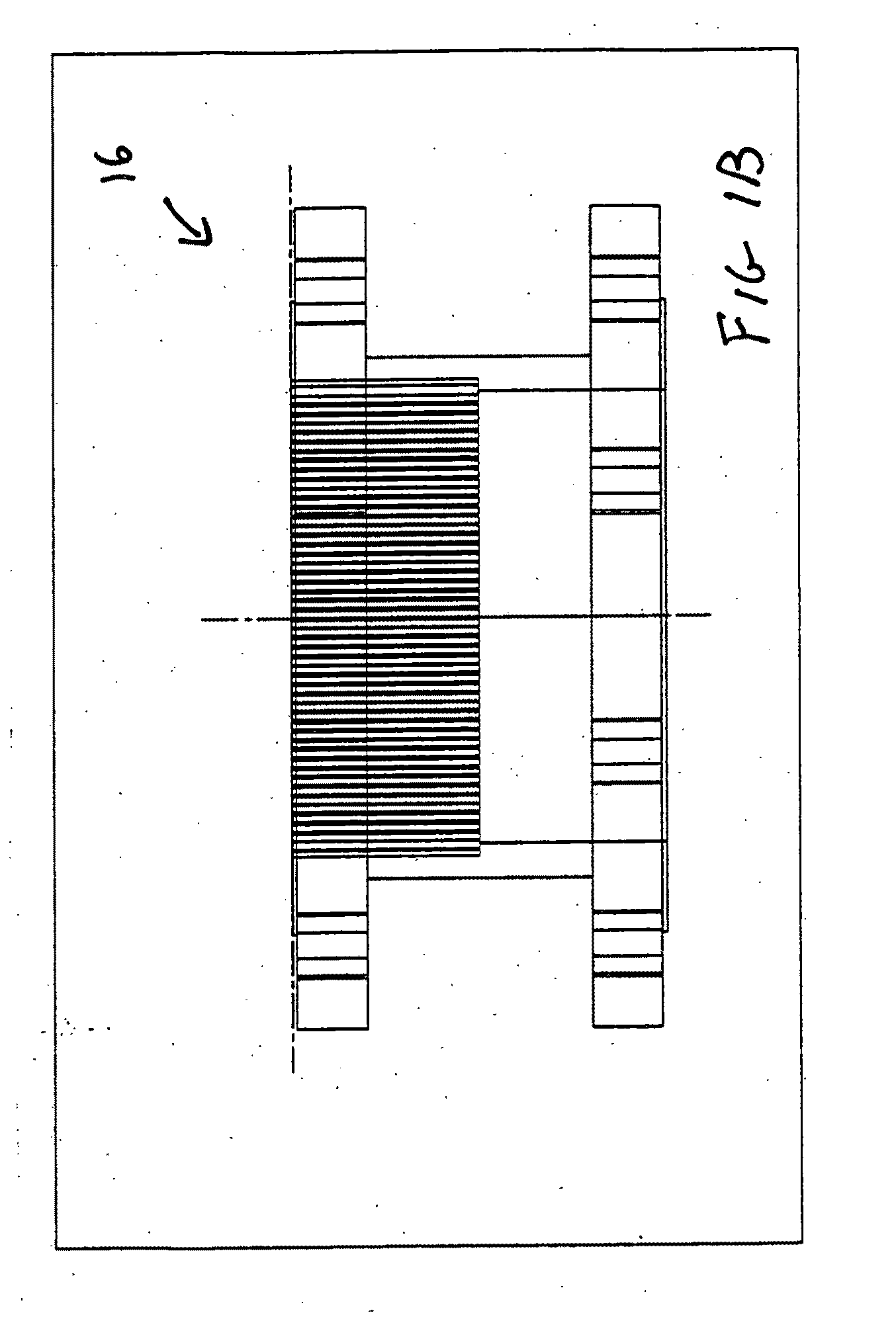
[0048]Referring now to the drawings wherein like reference numerals refer to similar or identical parts throughout the several views, and more specifically to FIGS. 1A, 1B, 2, 3A, 3B, 3C, 4A, 4B and 4C thereof, there is shown an exemplary apparatus 10 for determining fluid flow in a pipe 12. The apparatus 10 comprises an ultrasonic flowmeter 14 which communicates with the interior of the pipe 12 through at least one pair of apertures 18, where each aperture 18 of the one pair of apertures 18 has an effective diameter. The apparatus 10 comprises a turbulence conditioner 16 disposed in the pipe 12 having openings 22 where the pitch between openings 22 is a function of the effective diameter of the aperture 18.

[0049]The conditioner 16 has walls 20 between the openings 22 whose thickness can be a function of the pitch. The conditioner 16 has a length which can be a function of the pitch. The meter 14 can be disposed up to 3 internal pipe 12 diameters downstream of the conditioner 16. Th...


PUM

PropertyMeasurementUnit
Fractionaaaaaaaaaa
Fractionaaaaaaaaaa
Fractionaaaaaaaaaa

Abstract

An apparatus for determining fluid flow in a pipe includes an ultrasonic flowmeter which communicates with the interior of the pipe through at least one pair of apertures, where each aperture of the one pair of apertures has an effective diameter. The apparatus includes a turbulence conditioner disposed in the pipe having openings where the pitch between openings is a function of the effective diameter of the aperture. A turbulence conditioner for a pipe has openings and a pitch. The conditioner has walls between the openings whose thickness is a function of the pitch. The conditioner has a length which is a function of the pitch. A method for determining fluid flow in a pipe includes the steps of flowing fluid through a turbulence conditioner disposed in the pipe having openings where the pitch between openings, is made a function of an effective diameter of an aperture of an ultrasonic flowmeter which communicates with the interior of the pipe through the aperture. There is the step of measuring the flow with the meter. A method for producing a turbulence conditioner.

Description

FIELD OF THE INVENTION[0001]The present invention is related to the altering of the structure of turbulence in a pipe such that the turbulent variations of the fluid velocity, as measured by a transit time ultrasonic flow meter downstream of a turbulence conditioner, are much reduced. (As used herein, references to the “present invention” or “invention” relate to exemplary embodiments and not necessarily to every embodiment encompassed by the appended claims.) The reduction in turbulent velocity variations facilitates the “proving” of the ultrasonic meter—confirming its calibration against a standard—making it possible to confirm this calibration with significantly fewer runs of the prover than is possible with the same ultrasonic meter and the same prover operating without the turbulence conditioner.BACKGROUND OF THE INVENTION[0002]This section is intended to introduce the reader to various aspects of the art that may be related to various aspects of the present invention. The foll...

Claims


Application Information

Patent Timeline
IPC IPC(8): G01F1/66
CPCG01F1/662Y10T29/49G01F15/00G01F1/667
Inventor BROWN, GREGORESTRADA, HERBERTAUGENSTEIN, DONALD R.BERGSTROM, KEITH
Owner SENSIA LLC
Why Eureka
Try Eureka