
Post Support

a post and support technology, applied in the field of post support, can solve the problems of not easy to make adjustments to the post, not easy to reuse, etc., and achieve the effects of convenient post adjustment, convenient and fast adjustment, and convenient reusability and transportation

Inactive Publication Date: 2009-06-18
BLUEDOG FENCES AUSTRALIA HLDG
View PDF8 Cites 1 Cited by
  • Summary
  • Abstract
  • Description
  • Claims
  • Application Information

AI Technical Summary

Benefits of technology

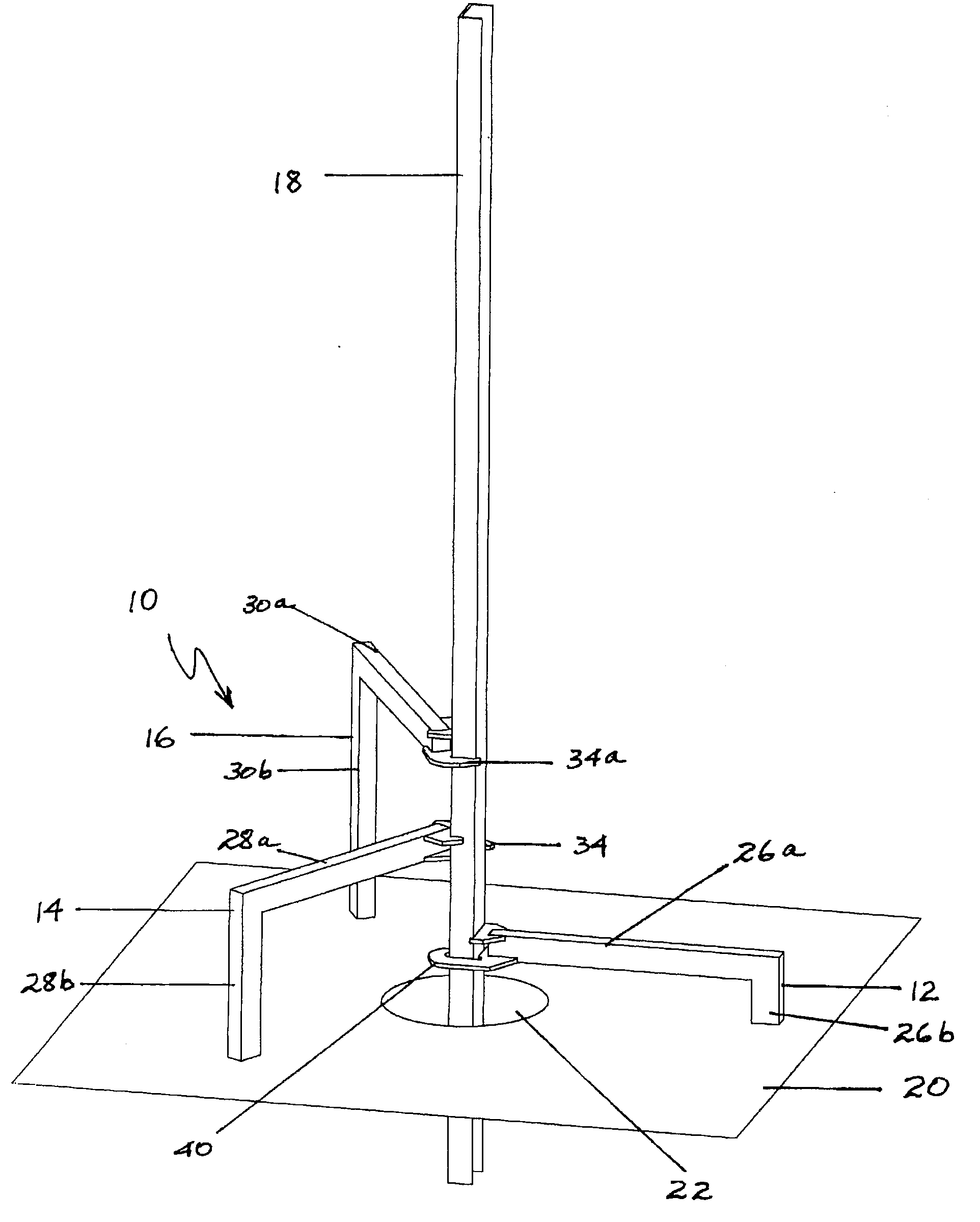
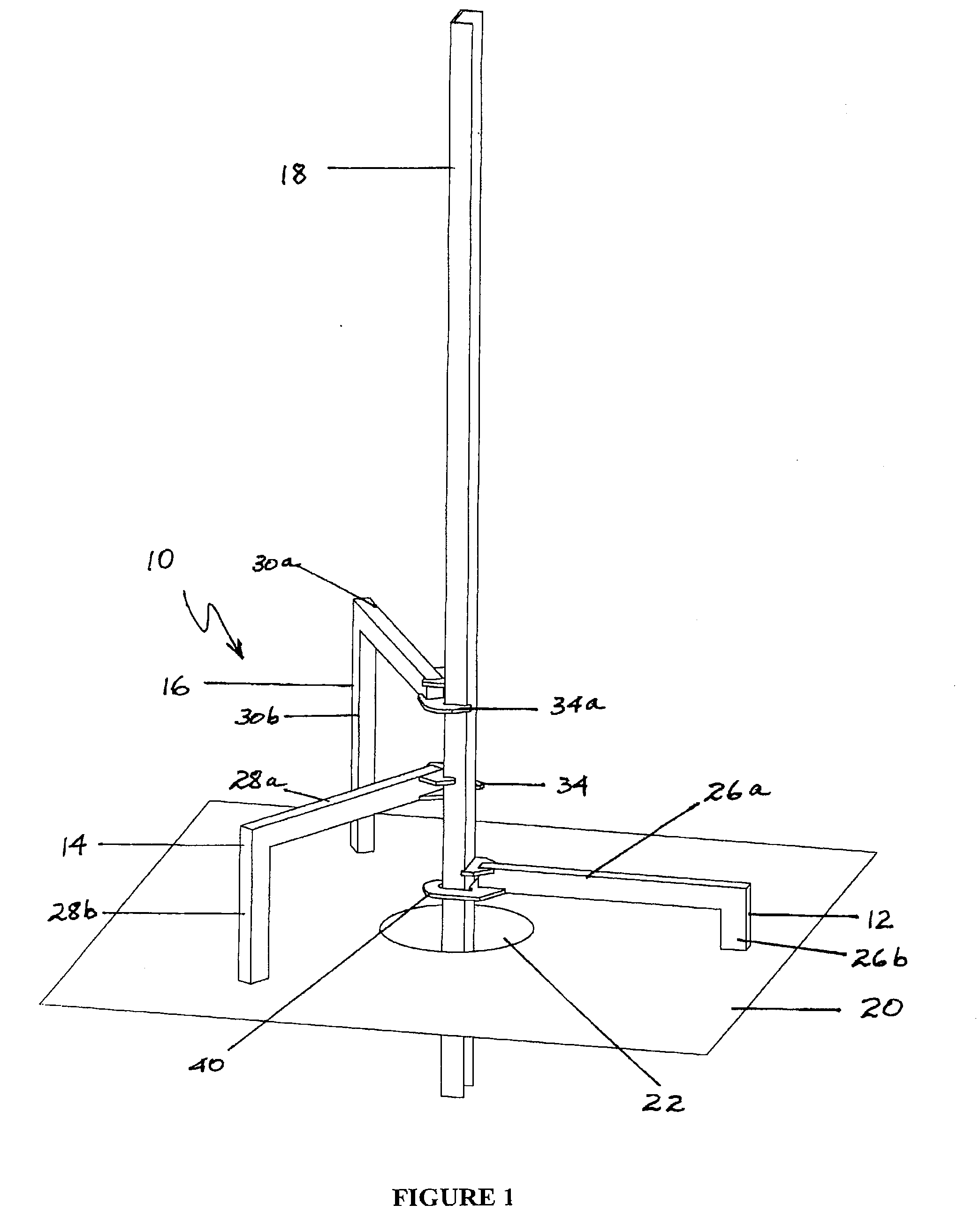
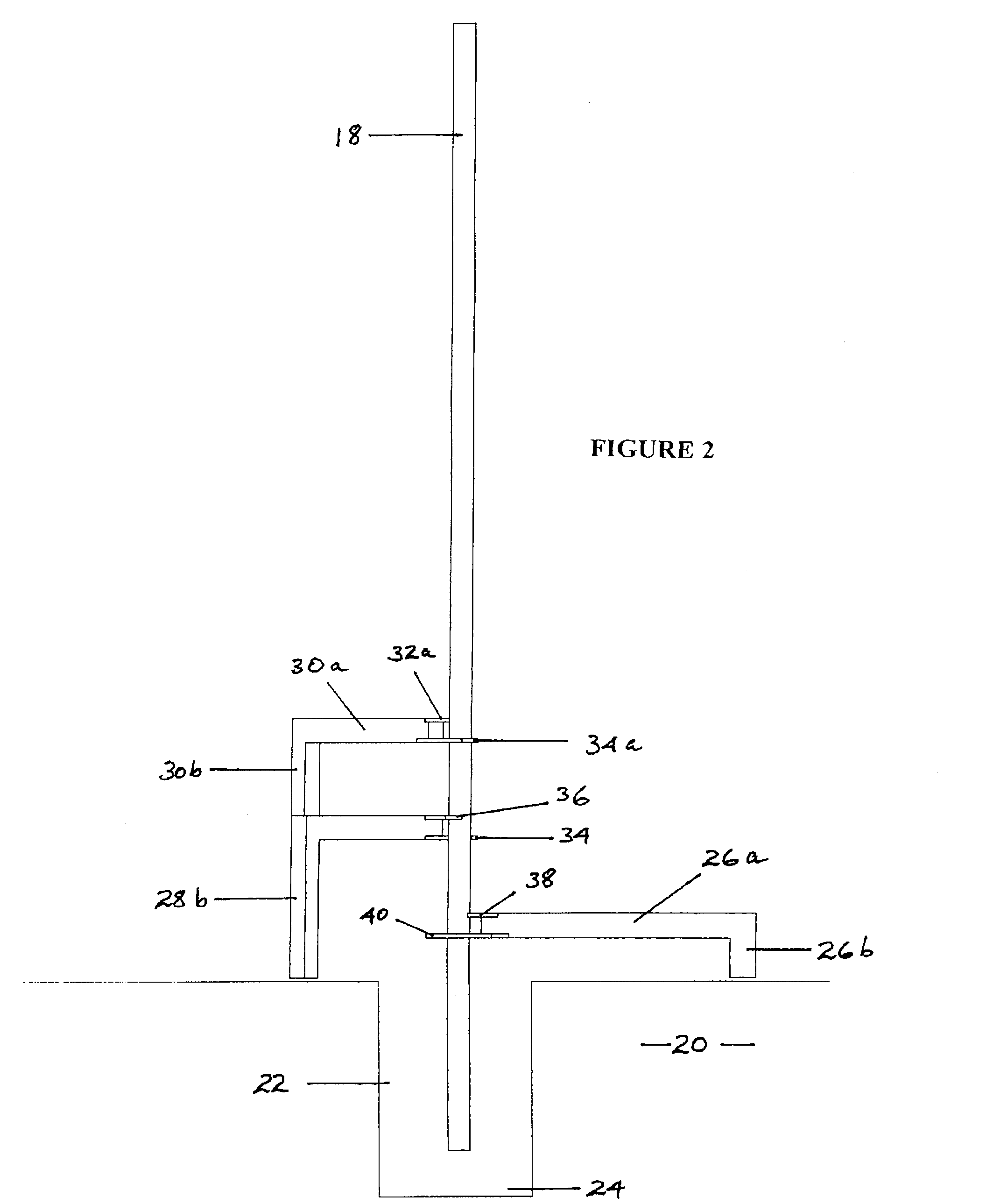
[0005]It is an object of the present invention to alleviate some or all of the problems found with prior art systems. In particular, it is an object of the present invention to provide a post support which, at least in some embodiments: can enable fast and easy post support; can enable a post to be adjusted to the correct position by a single workman; is readily reusable and transportable; can permit a post to be held free of the ground so that concrete can be poured underneath the post; can readily adjust for changes in terrain levels; and may permit relatively simple and fast adjustment as to height or angle.

Problems solved by technology

These and other prior art systems have suffered from one or more problems, for example: the support system is labor intensive and time consuming to construct; the support system requires two or more workmen (one to hold the post in position and other / s to construct the clamp and prop or other support system); the system is not easily reusable since most require assembly and disassembly after the post has been set; some systems do not suspend the post above the ground (which is desirable if the concrete is to be poured so that it sits under the post, so that a metal post will not rust); prior art systems may not easily allow for changes in levels of the terrain around the post; and it is not easy to make adjustments to the post as to height and angle.

Method used


Image

  • Post Support
  • Post Support
  • Post Support

Examples


Embodiment Construction

[0030]Accordingly, this invention provides a post support including: means for contacting a surface in or on which the post is to be set; brace means for contacting the post; and hook means for embracing the post.

[0031]The post may be of any desired length, cross sectional shape or material. Commonly, fence posts are made of timber and are square or rectangular in cross section or are made of steel and are RHS (rectangular hollow section) or L-, U-, or C-shaped in cross section. The invention is not limited to these shapes. For example, the post support of the invention may be used to support a post which is circular in cross section. If necessary, an adaptor, for example, a sleeve, may be used with the post support of the invention. The sleeve is preferably in two parts for positioning loosely around the post using, for example, a cable tie.

[0032]The surface in or on which the post is to be set will normally be earth, but the invention is not limited in this respect. For example, t...


PUM


Abstract

The invention provides a post support including means for contacting a surface in or on which the post is to be set. The post support has brace means for contacting the post and hook means for embracing the post. The invention also provides a post support system having two or more post supports, and a method of supporting a post in a chosen position.

Description

BACKGROUND OF THE INVENTION[0001]This invention relates to a post support. In particular, the invention concerns the type of support which may be used to support a post while it is being secured in, for example, the ground.[0002]In the description below, for convenience, reference will be made to posts intended to form parts of fences. It is to be understood, however, that the scope of the invention is not limited in this respect. The post support of the invention may be used in connection with any suitable type of post, including light poles, flag poles, building columns and the like, as well as fence posts.[0003]Commonly, fence posts are secured in the ground by the use of concrete. Single posts may be secured by a base of concrete limited to the area around the foot of the post. Where a number of posts is involved and a high degree of stability or security is required, a concrete footing, for example formed in a trench, may be included.[0004]As is well known, concrete requires se...

Claims


Application Information

Patent Timeline
Patent Type & Authority Applications(United States)
IPC IPC(8): F16M13/02
CPCE04H17/22E04H17/23
Inventor WEST, JAMES DAVID FRANCIS
Owner BLUEDOG FENCES AUSTRALIA HLDG
Learn More