RF energy harvesting circuit

Inactive Publication Date: 2009-06-18
THE STATE OF OREGON ACTING BY & THROUGH THE OREGON STATE BOARD OF HIGHER EDUCATION ON BEHALF OF OREGON STATE UNIV
View PDF21 Cites 139 Cited by
  • Summary
  • Abstract
  • Description
  • Claims
  • Application Information

AI Technical Summary

Benefits of technology

[0009]To address the current needs for a robust and efficient energy harvesting system, a voltage doubler rectifier RF power harvesting system is provided. The system includes at least one power harvesting module, where the power harvesting module has a voltage doubler rectifier structure circuit that includes a DC voltage input, a DC voltage output, a signal input, a first floating gate transistor and a second floating gate transistor, where the floating gate transistors are connected in series between the DC voltage input and the DC voltage output, and a gate control of the floating gate is connected to a drain of the transistor. The voltage double rectifier structure further includes a first capacitor disposed bet

Problems solved by technology

These biomedical implants generally operate within close proximity of the base station (typically 1-50 cm) and require robust designed since there is little tolerance for error in implanted devices.
RF powered devices are also used in ultra-low power sensor networks in remote areas to eliminate the need for batteries in the sensor system to keep the sensor network free of maintenance, however they may have a backup battery in case the power provided by the RF radiation is insufficient.
Far field RF powered devices are known to generally operate from distances of less than 10 meters from the RF source due to the high power loss from RF wave propagation at UHF frequencies.
Other known devices achieve sufficient power but provide low output voltage with higher load current making them inadequate for use in passively powered wireless sensor networks.
One of the major challenges to achieving this goal is the relatively high voltage requirement of rectifying circuits currently employed.

Method used


Image

  • RF energy harvesting circuit
  • RF energy harvesting circuit
  • RF energy harvesting circuit

Examples


Embodiment Construction

[0043]Although the following detailed description contains many specifics for the purposes of illustration, anyone of ordinary skill in the art will readily appreciate that many variations and alterations to the following exemplary details are within the scope of the invention. Accordingly, the following preferred embodiment of the invention is set forth without any loss of generality to, and without imposing limitations upon, the claimed invention.

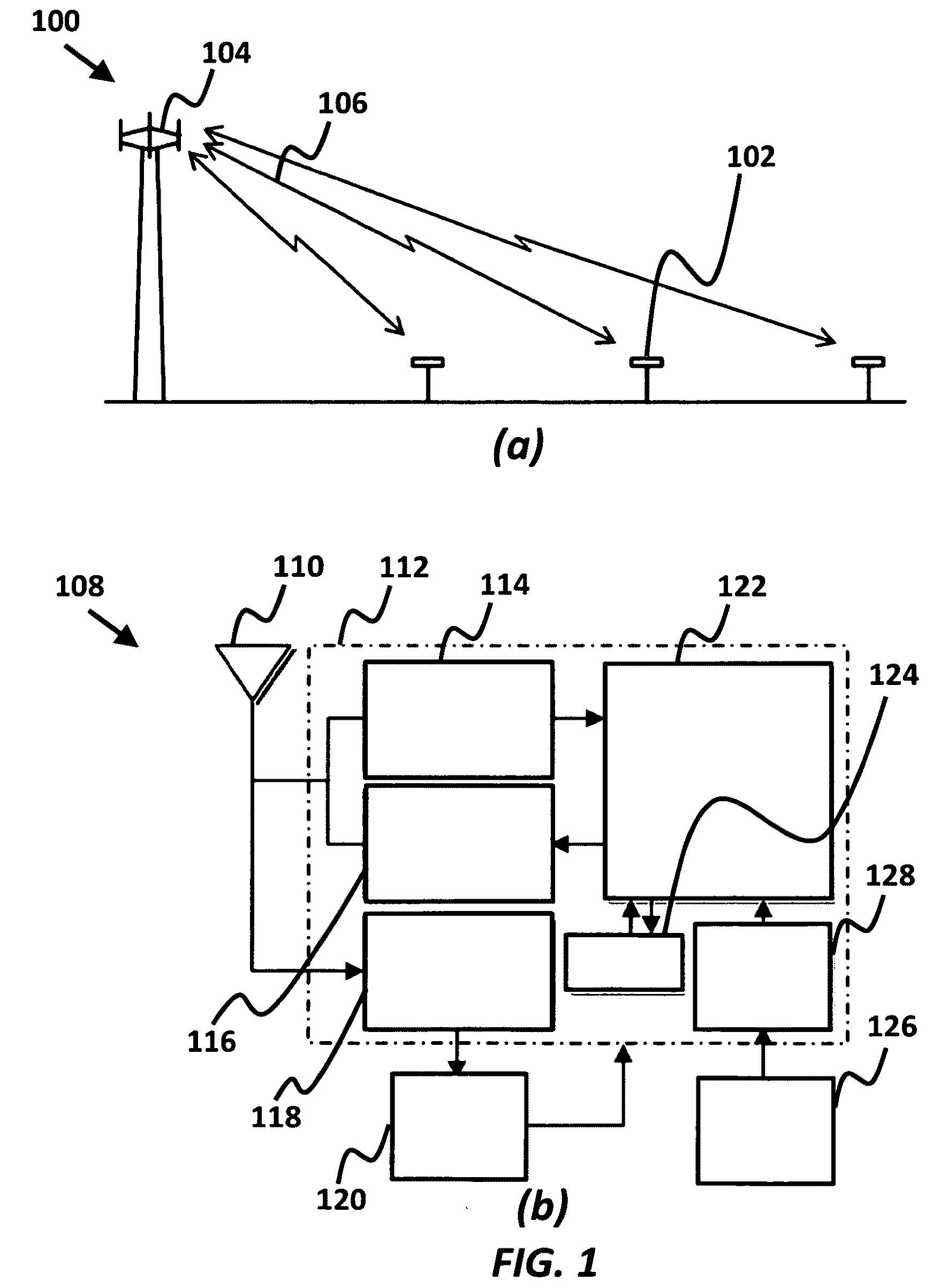
[0044]The present invention is directed to systems, circuitry and techniques for obtaining, recovering, acquiring and / or harvesting electrical energy from an environment having / including radio frequency (RF) signals (for example, signals in the is a frequency or rate of oscillation within the range of about 3 Hz and about 30 GHz). The RF signals may be periodic or non-periodic. The environment is generally described as being local to the system (for example, within a radius of 40 meters, and more preferably, within a radius of 3 meters). ...


PUM


Abstract

A voltage doubler rectifier RF power harvesting system is provided having at least one power harvesting module with a voltage doubler rectifier that includes a DC voltage input and output, signal input, first and second floating gate transistors that are connected in series between the DC voltage input and output, and a gate control of the floating gate is connected to a drain of the transistor. The voltage double rectifier includes a first capacitor disposed between the input signal and the drain of the first floating gate transistor, and a second capacitor disposed between a ground and the drain of the second floating gate transistor. The system includes an input antenna and a transmitter with a transmitter antenna, where a full-wave peak-to-peak voltage of an incoming RF signal is rectified. The system also includes a powered device connected to the DC voltage output to utilize the rectified signal.

Description

CROSS-REFERENCE TO RELATED APPLICATIONS[0001]This application is cross-referenced to and claims the benefit from U.S. Provisional Patent Application 60 / 961,009 filed Jul. 17, 2007, and from U.S. Provisional Patent Application 60 / 993,260 filed Sep. 10, 2007, which are hereby incorporated by reference.STATEMENT REGARDING FEDERALLY SPONSORED RESEARCH OR DEVELOPMENT[0002]The present invention was supported in part by grant number DBI-0529223 from the National Science Foundation (NSF). The U.S. Government has certain rights in the invention.FIELD OF THE INVENTION[0003]The invention relates generally to energy harvesting. More particularly, the invention relates to the conversion of radio frequency electromagnetic power to electrical power.BACKGROUND[0004]Power extraction is an increasingly important technology, especially in applications relating to harvesting power from propagating radio frequency (RF) signals. RF powered devices are often used in applications where battery replacement ...

Claims


Application Information

Patent Timeline
IPC IPC(8): H02M3/18H02J17/00
CPCH02M3/073H02J17/00H02J50/12H02J50/20H02J50/001H02J50/80
Inventor LE, TRIET TUFLEZ, TERRI S.MAYARAM, KARTIKEYA
Owner THE STATE OF OREGON ACTING BY & THROUGH THE OREGON STATE BOARD OF HIGHER EDUCATION ON BEHALF OF OREGON STATE UNIV
Why Eureka
Try Eureka