[0008]An
advantage of some aspects of the invention is that it provides a liquid supply device and a liquid ejecting apparatus capable of maintaining a decompressed state in a
decompression chamber even if a pump is stopped after decompressing the inside of the decompression chamber with the pump.
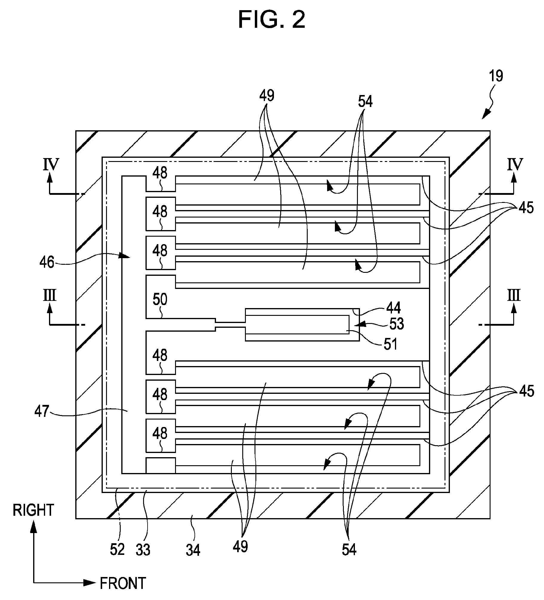
[0010]According to such a configuration, since the negative pressure occurs in the negative pressure chamber when suction in the negative pressure chamber is performed by a pump, the flexible member for negative pressure chamber is displaced by the negative pressure. Since the displacement of the flexible member for negative pressure chamber causes the communication hole valve body pressure member to press the communication hole valve body in the direction in which the communication hole valve body is in an open state, the communication hole is opened such that the negative pressure chamber and the decompression chamber communicate with each other through the communication hole. As a result, since suction in the decompression chamber is performed together with the negative pressure chamber by the pump, the decompression chamber becomes in a decompressed state. In addition, when the pump is stopped after the decompression chamber became in the decompressed state, the negative pressure of the negative pressure chamber is removed and the flexible member for negative chamber returns to the original position. Then, since the communication hole valve body biasing member biases the communication hole valve body in the direction in which the communication hole valve body is closed, the communication hole is closed such that the negative pressure chamber and the decompression chamber do not communicate with each other. As a result, the decompressed state of the decompression chamber is maintained. Therefore, it becomes possible to maintain the decompression chamber in the decompressed state even if the pump is stopped after decompressing the decompression chamber with the pump.
[0012]According to such a configuration, since the negative pressure occurs in the negative pressure chamber when suction in the negative pressure chamber is performed by a pump, the flexible member for negative pressure chamber is displaced by the negative pressure. Since the displacement of the flexible member for negative pressure chamber causes the communication hole valve body pressure member to press the communication hole valve body in the direction in which the communication hole valve body is in an open state, the communication hole is opened so that the negative pressure chamber and the decompression chamber communicate with each other through the communication hole. As a result, since suction in the decompression chamber is performed together with the negative pressure chamber by the pump, the decompression chamber becomes in a decompressed state. In addition, when the pump is stopped after the decompression chamber became in the decompressed state, the negative pressure of the negative pressure chamber is removed and the flexible member for negative chamber returns to the original position. Then, since the communication hole valve body biasing member biases the communication hole valve body in the direction in which the communication hole valve body is closed, the communication hole is closed such that the negative pressure chamber and the decompression chamber do not communicate with each other. As a result, the decompression state of the decompression chamber is maintained. Therefore, it becomes possible to maintain the decompression chamber in the decompressed state even if the pump is stopped after decompressing the decompression chamber with the pump.
[0014]According to such a configuration, when the amount of liquid in the pressure chamber decreases as the liquid is consumed at the downstream side, the negative pressure occurs in the pressure chamber. Then, the flexible member for pressure chamber is displaced by the negative pressure. Since the displacement of the flexible member for pressure chamber causes the inflow hole valve body pressure member to press the inflow hole valve body in the direction in which the inflow hole valve body is in an open state, the inflow hole is opened such that the liquid is supplied from the upstream side into the pressure chamber, and the negative pressure within the pressure chamber is removed. Then, since the flexible member for pressure chamber returns to the original position, the inflow hole valve body biasing member biases the inflow hole valve body in the direction in which the inflow hole valve body is in a
closed state. As a result, the inflow hole is closed to stop the supply of the liquid into the pressure chamber. Therefore, since the negative pressure chamber is provided in parallel with the pressure chamber that forms a part of the liquid supply path and the flexible member for negative pressure chamber and the flexible member for pressure chamber are integrally formed, it becomes possible to reduce the number of components and to make the device small compared with a case where the flexible member for negative pressure chamber and the flexible member for pressure chamber are formed of separate members.
[0016]According to such a configuration, it becomes possible to reduce the number of components compared with a case where the communication hole valve body pressure member and the inflow hole valve body pressure member are formed of separate members.
[0018]According to such a configuration, since the
adhesive is not exposed to the outside, the
adhesive is not influenced by the external environment. As a result, since deterioration of the
adhesive can be suppressed, a decrease in adhesive strength of the adhesive can be suppressed. In addition, by covering the adhesive with a member not allowing liquid to permeate therethrough,
evaporation of the liquid to the outside can be suppressed without being influenced by the liquid permeability of the adhesive.


