Information processing apparatus and its control method

a technology of information processing apparatus and control method, which is applied in the direction of generating/distributing signals, digital output to print units, multi-programming arrangements, etc., can solve problems such as electric power, and achieve the effect of suppressing distributed processing and consuming power

Inactive Publication Date: 2005-12-15
CANON KK
View PDF12 Cites 17 Cited by
  • Summary
  • Abstract
  • Description
  • Claims
  • Application Information

AI Technical Summary

Benefits of technology

[0013] According to the aforementioned apparatus and processing, consumption power when target devices of the distributed processing execute the distributed processing can be suppressed.

Problems solved by technology

However, in case of target devices of the aforementioned distributed processing, modules which are not required for the distributed processing waste electric power if the device is resumed to the normal operation to attain the distributed processing.
However, this distributed processing divides pages or copies to be printed and makes a plurality of devices execute processes up to printing of the divided pages or copies, and a device designated by a client does not print all pages or copies.

Method used


Image

  • Information processing apparatus and its control method
  • Information processing apparatus and its control method
  • Information processing apparatus and its control method

Examples


first embodiment

[Printer]

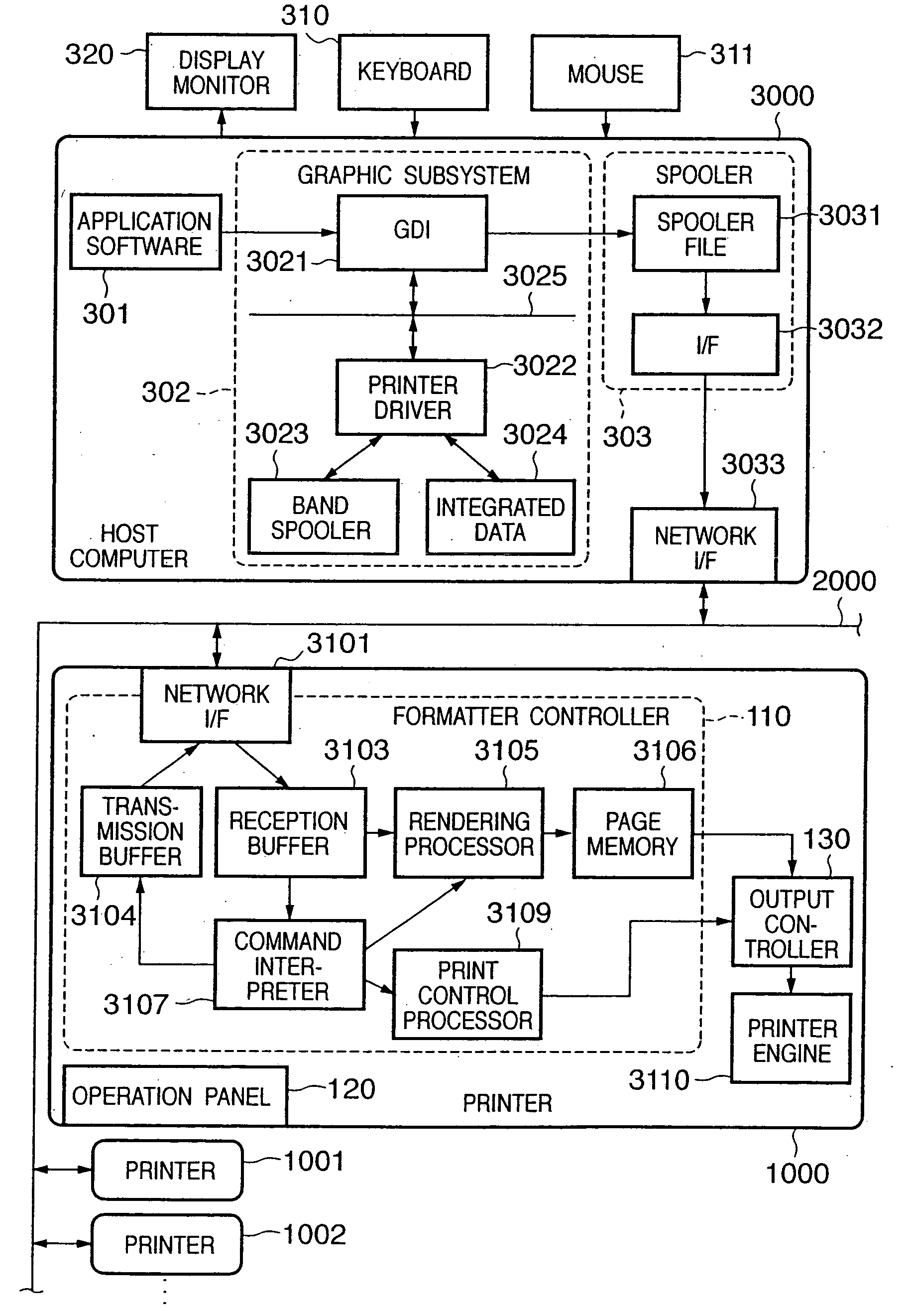
[0036]FIG. 3 shows the structure of a printer 1000 according to this embodiment. Note that this embodiment can be applied to a network environment to which a plurality of multi-functional peripheral equipments (MFPs), copying machines, and laser beam and ink-jet printers are connected. A color laser beam printer (to be simply referred to as a “printer” hereinafter) will be exemplified below as a typical printer. The printer 1000 shown in FIG. 3 prints an image at a recording density of 600 dpi on the basis of multi-valued data which expresses pixels of respective color components by 8-bit grayscale.

[0037] Referring to FIG. 3, the printer 1000 receives and stores a print command, which is supplied from an externally connected host computer 200, and includes print data (character codes, image data, PDL data, or the like) and a control code. The printer 1000 forms a character pattern, image, or the like in accordance with the received print command, and forms a color visible...

second embodiment

[0091] The second embodiment according to the present invention will be described below. In the second embodiment, the same reference numerals denote the same components as those in the first embodiment, and a detailed description thereof will be omitted.

[0092] As the difference in the second embodiment from the first embodiment, a power controller 516 that performs power control is added to the printer 1000, as shown in FIG. 10, and an interrupt signal 515 of the LANC 509 upon reception of a packet from the network 2000 is input to the power controller 516. The power controller 516 has a function of turning on / off electric power to be supplied to modules other than the LANC 509, and can restart stopped power supply when it receives the interrupt signal 515 from the LANC 509.

[0093] Assume that the TM 3034 inputs a divided process to the printer 1000. Also, the TM 3034 acquires the resource information of the printer 1000 from the broker 1003 and RM 1004 which run on the printer 10...

third embodiment

[0100] The third embodiment according to the present invention will be described below. In the third embodiment, the same reference numerals denote the same components as those in the first and second embodiments, and a detailed description thereof will be omitted.

[0101] As the difference in the third embodiment from the first embodiment, a hard disk interface (HD I / F) 517 and hard disk driver (HDD) 518 are added to the printer 1000, as shown in FIG. 12. The CPU 501 can read / write data between the RAM 503 and HDD 518 by controlling the HD I / F 517.

[0102]FIG. 13 is a flowchart for explaining the consumption power control of a device to which a divided process is input. Since the printer 1000 executes a normal process before input of the divided process, electric power is supplied to respective modules, and the clock controller 514 supplies clocks of the normal operation frequency to the respective modules.

[0103] The CPU 501 checks if an interrupt from the LANC 509 has occurred (S90...


PUM


Abstract

When a target device of distributed processing has shifted to a power save mode, if the target device is resumed to the normal operation to attain the distributed processing, resources of the target device which are not required for the distributed processing waste electric power. Therefore, when a print job to be processed by grid processing is received, resources required for the grid processing from resources in a waiting state, and the grid processing is executed to process the received print job.

Description

FIELD OF THE INVENTION [0001] The present invention relates to an information processing apparatus and its control method and, more particularly, to a case wherein the distributed load system of grid computing is applied to an information processing apparatus such as printers, multi-functional peripheral equipment, and the like connected to a computer network. BACKGROUND OF THE INVENTION [0002]FIG. 1 is a diagram for explaining the architecture of grid computing. There are several types of grids. A grid described below is of the type called a desktop grid, which executes a job by utilizing an idle time of a CPU of a desktop PC or the like. [0003] A client PC shown in FIG. 1 inputs a job in accordance with a user's instruction (S1). That request (job) is passed to a task manager (to be abbreviated as “TM” hereinafter), which informs a dynamic job scheduler (to be abbreviated as “DJS” hereinafter) of the contents (job request) (S2). The DJS which manages the resources of the overall g...

Claims


Application Information

Patent Timeline
Patent Type & Authority Applications(United States)
IPC IPC(8): G06F15/177G06F1/04G06F1/32G06F3/12G06F9/46G06F15/00G06K15/00
CPCG06F3/1215G06F3/1221G06F3/124G06F3/1241G06K15/1803G06F3/1279G06F3/1285G06K15/00Y02B60/1271G06F3/1244Y02D10/00G06F3/12G06F13/00
Inventor YASUDA, MASATAKAMATSUKUBO, YUSHISHIMIZU, YUKIHIKOKOBAYASHI, NORIYUKIMAEKAWA, SHINICHIRONAMIKATA, TAKESHISAKAI, HIDEKITASHIRO, HIROHIKOMATSUMOTO, ATSUSHIAKASHI, MASAMICHI
Owner CANON KK
Why Eureka
Try Eureka