Communication appartus

Inactive Publication Date: 2009-12-31
RENESAS ELECTRONICS CORP
View PDF1 Cites 18 Cited by
  • Summary
  • Abstract
  • Description
  • Claims
  • Application Information

AI Technical Summary

Benefits of technology

[0008]Furthermore, the communication apparatus of the present embodiment can identify each clock that can sample the sync word correctly from among plural clocks. Then, the apparatus selects a single clock of the identified clocks to sample the transmission signal and outputs an instruction for stopping the supply of other not-selected clocks. Upon receiving the clock stop instruction, the subject unit of the communication a

Problems solved by technology

And when in high speed synchronous communications between the high frequency LSI and the baseband LSI configured as described above, sometimes such troubles as signal delays and jittering occur in the transmission path.
At this time, if communications are made

Method used


Image

  • Communication appartus
  • Communication appartus
  • Communication appartus

Examples


Example

First Embodiment

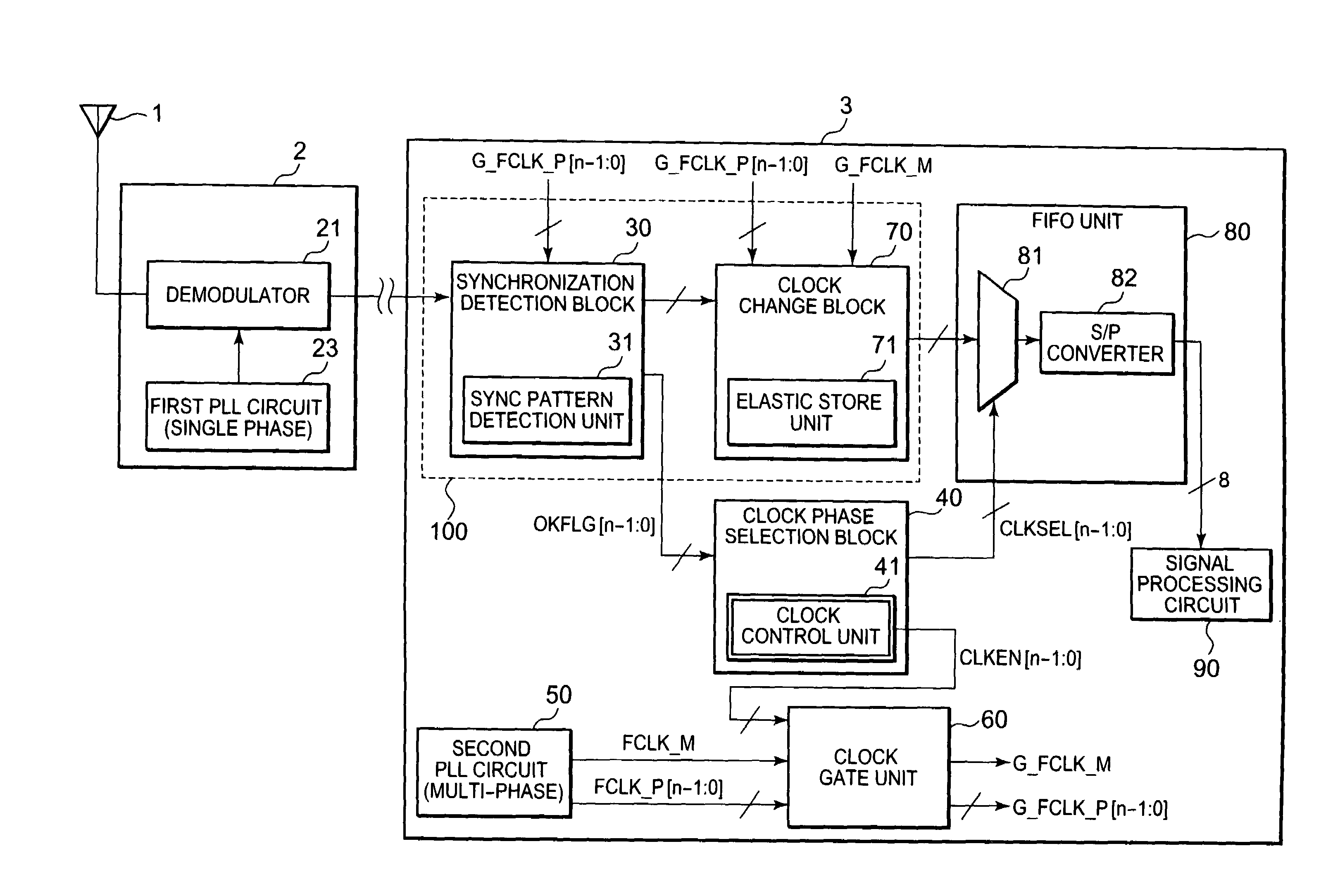
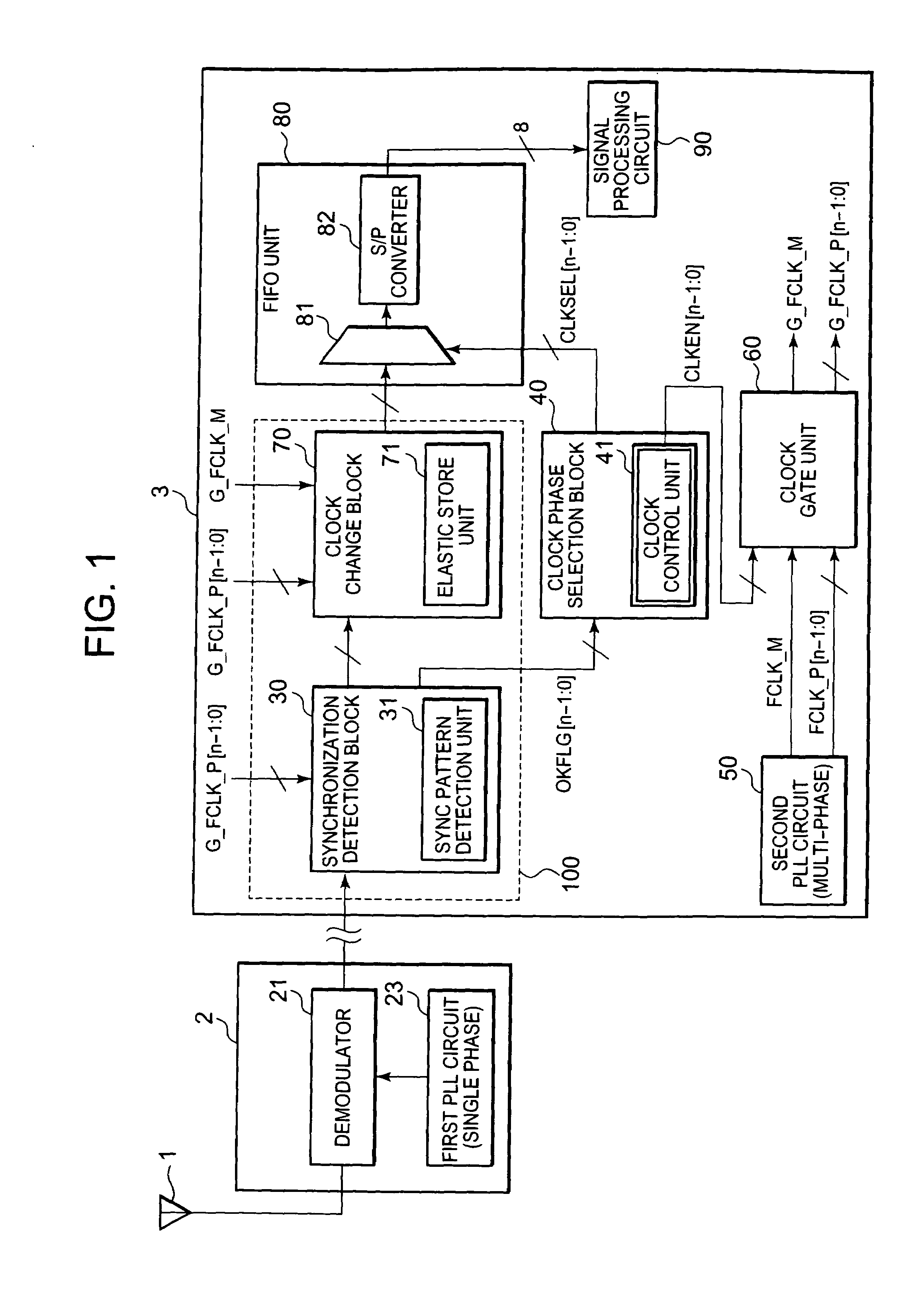
[0021]Hereunder, there will be described the preferred embodiments of the present invention in detail with reference to the accompanying drawings. At first, there will be described a configuration of a communication apparatus (a receiving apparatus concretely) in this first embodiment. As shown in FIG. 1, the receiving apparatus includes an antenna 1, a high frequency (RF) unit 2, and a digital baseband (DBB) unit 3.

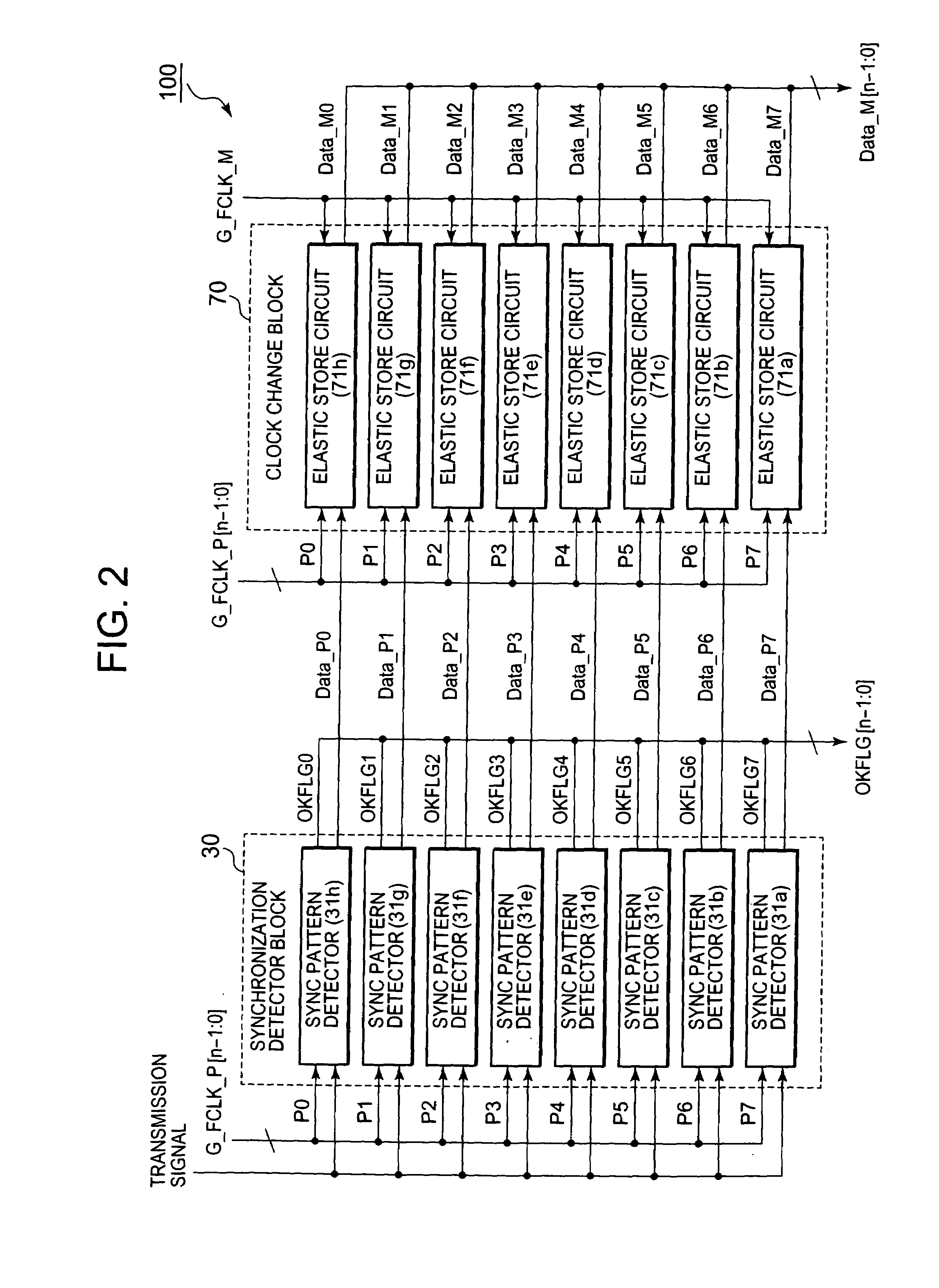
[0022]The RF unit 2 includes a demodulator 21 and a first PLL (Phase Locked Loop) circuit 23. The demodulator 21 demodulates radio signals received through the antenna 1 to generate data signals. Each of the data signals is parallel data signal having, for example, an 8-bit width. The demodulator 21 converts those parallel data to serial data and outputs the converted data as transmission signals. Each transmission signal consists of a data string having a single-bit width, for example.

[0023]The transmission signal in this first embodiment includes a sync...

Example

Second Embodiment

[0045]Next, there will be described a configuration of a communication apparatus (concretely, a receiving apparatus) in this second embodiment with reference to FIG. 8. In FIG. 8, the same reference numerals will be used for the same components as those shown in FIG. 1 in the first embodiment described above. The receiving apparatus includes an antenna 1, a high frequency (RF) unit 2, and a digital baseband (DBB) unit 3. The configurations and functions of the antenna 1 and the RF unit 2 are the same as those in the first embodiment, so their descriptions will be omitted here.

[0046]Each transmission signal in this second embodiment includes a sync word region, a header region, and a payload region in its data string. The sync word region stores the sync word set beforehand in the subject system. The header region stores various control information items used to control the system. The payload region stores data to be processed in the system. The system receives the ...


PUM


Abstract

A communication apparatus which includes a clock generation circuit outputting a plurality of clocks, each of said plurality of clocks having a different phase from each other; a synchronization detection block receiving a sync word and a payload having a predetermined length after receiving said payload, sampling said sync word by using each of said plurality of clocks and to output a first signal indicating a clock or clocks capable of sampling said sync word successfully, said synchronization detection block being capable of sampling said payload by using a clock or clocks inputted thereinto; a clock phase selection block coupled to said synchronization detection block to-receive said first signal to select one of said plurality of clocks in accordance with said first signal and to output a second signal indicating a selected clock; and a clock gate unit coupled between said clock generation circuit and said synchronization detection block and coupled to said clock phase selection block to receive each of said plurality of clocks and said second signal to output said selected one of said plurality of clocks to said synchronization detection block and not to output a rest of said plurality of said clocks based on said second signal during a period corresponding to said predetermined length of said payload.

Description

FIELD OF THE INVENTION[0001]The present invention relates to a communication apparatus that uses multi-phase clocks to detect synchronization and more particularly to a communication apparatus that stops all the clocks that are not required for sampling transmission signals, respectively.BACKGROUND OF THE INVENTION[0002]A radio communication LSI consists of a high frequency (RF) LSI and a baseband (BB) LSI. The high frequency LSI processes signals received by an antenna as analog signals. The baseband LSI processes transmission signals as digital signals before modulation or after demodulation.[0003]And when in high speed synchronous communications between the high frequency LSI and the baseband LSI configured as described above, sometimes such troubles as signal delays and jittering occur in the transmission path. At this time, if communications are made according to clock signals that are asynchronous between those LSIs, the receiving side LSI often fails in correct receiving of d...

Claims


Application Information

Patent Timeline
IPC IPC(8): H04L7/00
CPCH04L7/042
Inventor KONISHI, SHINYAARAI, NORIO
Owner RENESAS ELECTRONICS CORP
Why Eureka
Try Eureka