Stereo Camera Device

a camera and stereo technology, applied in the field of stereo camera devices, can solve the problems of low accuracy, increased image processing load, and objects that cannot be included in the processing area, and achieve the effect of suppressing image processing load

Active Publication Date: 2009-06-18
HITACHI ASTEMO LTD
View PDF20 Cites 35 Cited by
  • Summary
  • Abstract
  • Description
  • Claims
  • Application Information

AI Technical Summary

Benefits of technology

[0020]The present invention makes it possible to detect objects depending on the driving environment and simultaneously to suppress load on image processing.

Problems solved by technology

For this reason, the farther an object is located, the more significant effect the object will have to the extent that an erroneous calculation even by one pixel will greatly affect the result and lower the accuracy.
However, the use of a high-resolution type image pickup device will result in an increased load on image processing.
If a predetermined window is used disregarding such factors as speed and other driving conditions, there is a possibility that objects may not be included in the processing area and resultantly may not be detected.

Method used


Image

  • Stereo Camera Device
  • Stereo Camera Device
  • Stereo Camera Device

Examples


Embodiment Construction

[0039]Explanation is given hereinbelow of the stereo camera device in regard to the configuration and the performance in reference to FIG. 1 to FIG. 10B.

[0040]In the beginning, FIG. 1 is referred to in explaining the configuration of the vehicle-mounted system of the stereo camera device according to the embodiment of the present invention.

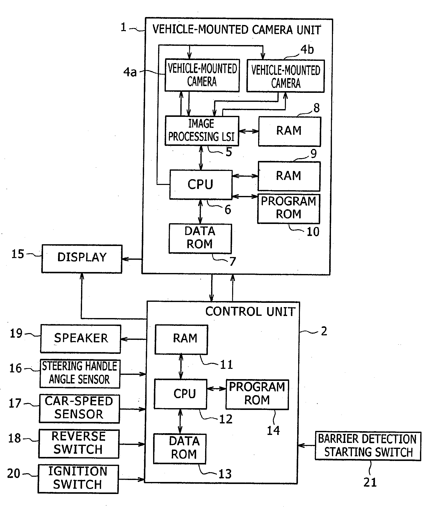
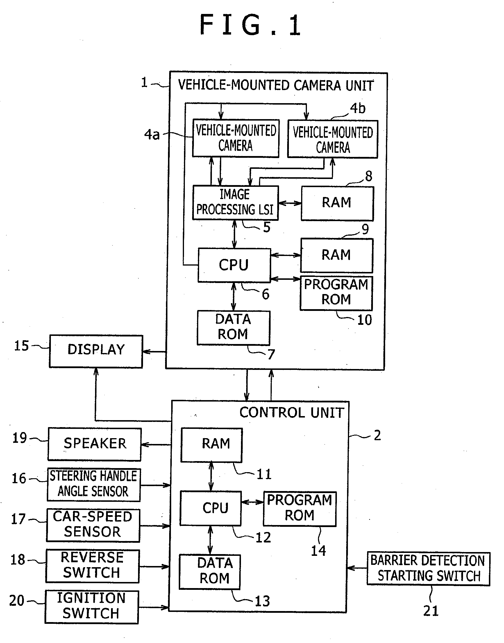
[0041]FIG. 1 is a system block diagram showing the configuration of the vehicle-mounted system of the stereo camera device

[0042]The vehicle-mounted system according to this embodiment is composed of the vehicle-mounted camera unit 1 and the control unit 2. The vehicle-mounted camera unit 1 is the stereo camera device according to this embodiment. The vehicle-mounted camera unit 1, by means of the vehicle-mounted cameras (image pickup device) 4a and 4b, recognizes the environment surrounding the vehicle (the subject vehicle) mounted with the vehicle-mounted camera unit 1. The vehicle-mounted cameras (image pickup device) 4a and 4b are, for example,...


PUM


Abstract

A stereo camera device includes: plural picture image taking sections, an image correction section which makes correction of picture images taken, a parallax calculating section which calculates parallax, an amount of dislocation between the left and right images, and an image recognition section which carries out image recognition processing using both the image taken and the calculated parallax, or either of them. The stereo camera device further includes: a processing area setting up section which sets up the image area to be processed and reduction ratio differently depending on the driving environment of the vehicle on which the stereo camera device is mounted, wherein, by using the image area and the reduction ratio set up by the processing area setting up section, the image correction section makes correction to the picture image, the parallax calculating section calculates parallax, and the image recognition section carries out processing of image recognition.

Description

BACKGROUND OF THE INVENTION[0001]This invention relates to a stereo camera device and in particular to a stereo camera device suitable for being fitted with a high-resolution type image pickup device.[0002]In recent years, a object detection device which utilizes a stereo camera to detect pedestrians, vehicles, and objects has been put to practical use. This device checks a plurality of images taken at the same time and calculates displacements (parallax differences) of a same object on each image by template matching. Based on the calculated parallax difference obtained from the above, it is possible also to calculate the positions of the object in the real space by a well-known conversion equation.[0003]The stereo camera device of the present invention uses a pair of images photographed by two sets of image-taking means to recognize the object by calculating the distance to the object. The stereo camera device having the abovementioned function is beginning to find applications fo...

Claims


Application Information

Patent Timeline
Patent Type & Authority Applications(United States)
IPC IPC(8): H04N7/18G06K9/00
CPCG06K9/00805G06V20/58
Inventor HIGUCHI, MIRAIMURAMATSU, SHOJIYOKOTA, SOICHIROMONJI, TATSUHIKO
Owner HITACHI ASTEMO LTD
Why Eureka
Try Eureka