Wind direction-adjustable heat-dissipation fan module

a heat dissipation fan and wind direction technology, which is applied in the direction of cooling/ventilation/heating modifications, electrical apparatus casings/cabinets/drawers, instruments, etc., can solve the problems of difficult to meet the needs of fixed type heat dissipation fans, difficult to move the electric fan, and high heat generation of electronic devices during operation, so as to achieve better heat dissipation efficiency

Inactive Publication Date: 2009-06-18
TOPOWER COMP INDUSTRAIL
View PDF13 Cites 45 Cited by
  • Summary
  • Abstract
  • Description
  • Claims
  • Application Information

AI Technical Summary

Benefits of technology

[0005]To achieve the abovementioned objective, the present invention proposes a wind direction-adjustable heat-dissipation fan module, which comprises a support unit arranged inside a computer. An electric fan is pivotally installed in the support unit, and the electric fan can have a rotation trip with respect to the support unit. According to the layout of the electronic devices inside the computer, the electric fan can be rotated pivotally with respect to the support unit to adjust the angle of the wind outlet to attain better heat-dissipation efficiency.

Problems solved by technology

Those electronic devices generate a great amount of heat during operation.
The abovementioned fixed type heat-dissipation fan arranged in the front or rear side of a computer cannot be adjusted to provide air current with a specified wind direction for a specified area inside the computer but can only provide air current of a fixed wind direction.
The fixed type heat-dissipation fans have been hard to meet the need.
However, the mobile heat-dissipation device is installed in the motherboard, and the movement field of the electric fan is likely to be limited by the electronic devices on the motherboard (such as CPU, memories, etc.), which disadvantages the heat-dissipation effect of the conventional technology.
However, the position of the electric fan cannot be arranged according to the layout of the electronic devices inside a computer but is limited by the insertion portions of the connection member.

Method used


Image

  • Wind direction-adjustable heat-dissipation fan module
  • Wind direction-adjustable heat-dissipation fan module
  • Wind direction-adjustable heat-dissipation fan module

Examples


Embodiment Construction

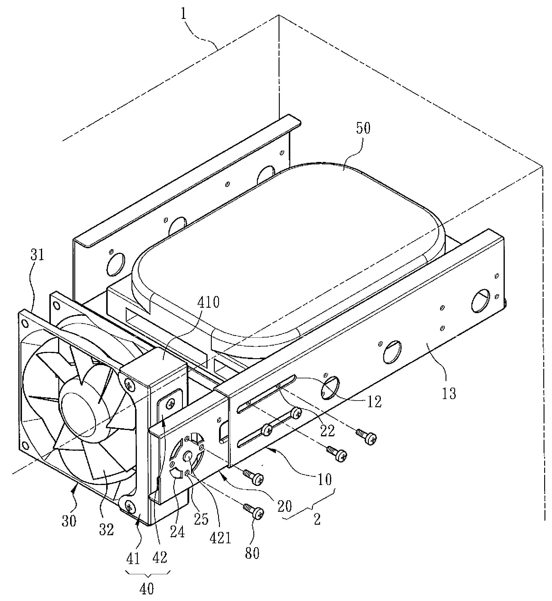
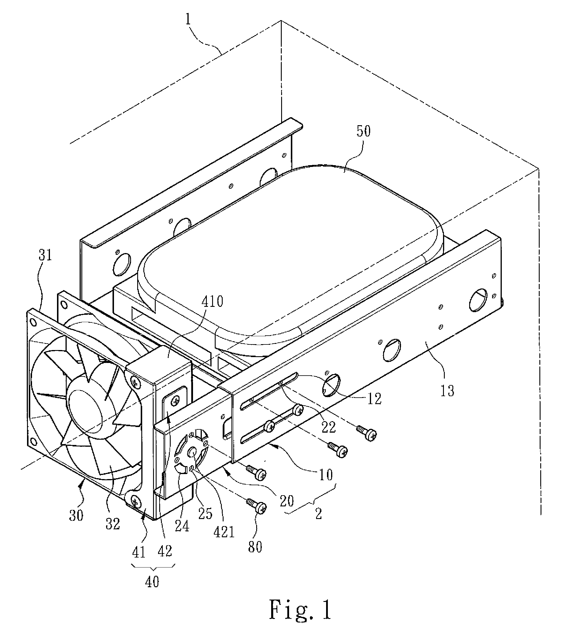
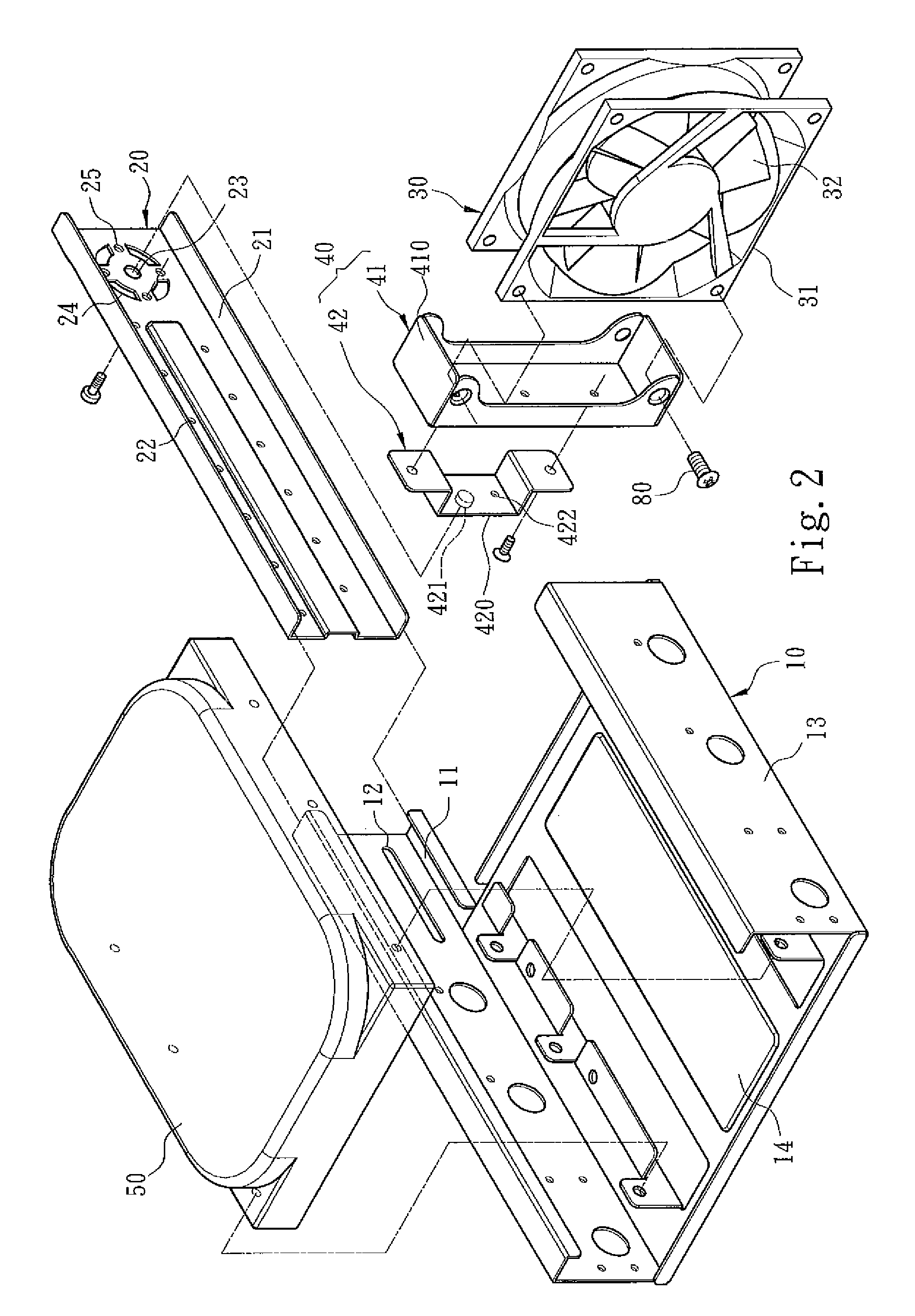
[0012]Below, the technical contents of the present invention will be described in detail in cooperation with the drawings.

[0013]Refer to FIG. 1, FIG. 2 and FIG. 3. The present invention proposes a wind direction-adjustable heat-dissipation fan module, which comprises a support unit 2 arranged inside a computer 1. An electric fan 30 is pivotally installed in the support unit 2, and the electric fan 30 has a rotation trip with respect to the support unit 2 for adjusting the angle of the wind outlet. In the present invention, the support unit 2 has a fixed frame 10 arranged inside the computer 1 and at least one moveable frame 20 installed in the fixed frame 10, wherein the electric fan 30 is pivotally installed in the moveable frame 20. The fixed frame 10 has a slide rail 11, and the moveable frame 20 has a slide member 21 corresponding to the slide rail 11. Via the slide rail 11 and the slide member 21, the moveable frame 20 can have a translation trip with respect to the fixed frame...


PUM


Abstract

The present invention discloses a wind direction-adjustable heat-dissipation fan module, which is arranged inside a computer and provides heat-dissipation air current for electronic devices inside the computer. The wind direction-adjustable heat-dissipation fan module of the present invention comprises a support unit arranged inside the computer. An electric fan is pivotally coupled to the support unit, and the electric fan can have a rotation trip with respect to the support unit. According to the layout of the electronic devices inside the computer, the electric fan can be rotated pivotally with respect to the support unit to adjust the angle of the wind outlet. The present invention can solve the incapability of the conventional heat-dissipation fan to adjust the angle thereof, which causes inferior heat-dissipation inside a computer.

Description

FIELD OF THE INVENTION[0001]The present invention relates to a wind direction-adjustable heat-dissipation fan module, particularly to a wind direction-adjustable heat-dissipation fan module, which is installed inside a computer, wherein the position and direction of the heat-dissipation fan can be adjusted to provide appropriate air current for the electronic devices inside the computer.BACKGROUND OF THE INVENTION[0002]There are various electronic devices installed inside a computer, such as hard drives, CPU, power supplies, PCBs having many electronic elements thereon, etc. Those electronic devices generate a great amount of heat during operation. Thus, heat-dissipation fans are used to keep the electronic devices working at an appropriate temperature. Generally, a heat-dissipation fan is arranged in the front or rear side of a computer to suck in external cool air and expel hot air inside the computer so that the temperature of the electronic devices can be cooled down.[0003]The a...

Claims


Application Information

Patent Timeline
Patent Type & Authority Applications(United States)
IPC IPC(8): H05K7/20
CPCG06F1/187H05K7/20172G06F1/20
Inventor CHEN, MICHAEL
Owner TOPOWER COMP INDUSTRAIL
Why Eureka
Try Eureka