
Residual frequency offset compensation apparatus using phase shift compensation scheme

Inactive Publication Date: 2009-06-18
ELECTRONICS & TELECOMM RES INST
View PDF3 Cites 12 Cited by
  • Summary
  • Abstract
  • Description
  • Claims
  • Application Information

AI Technical Summary

Benefits of technology

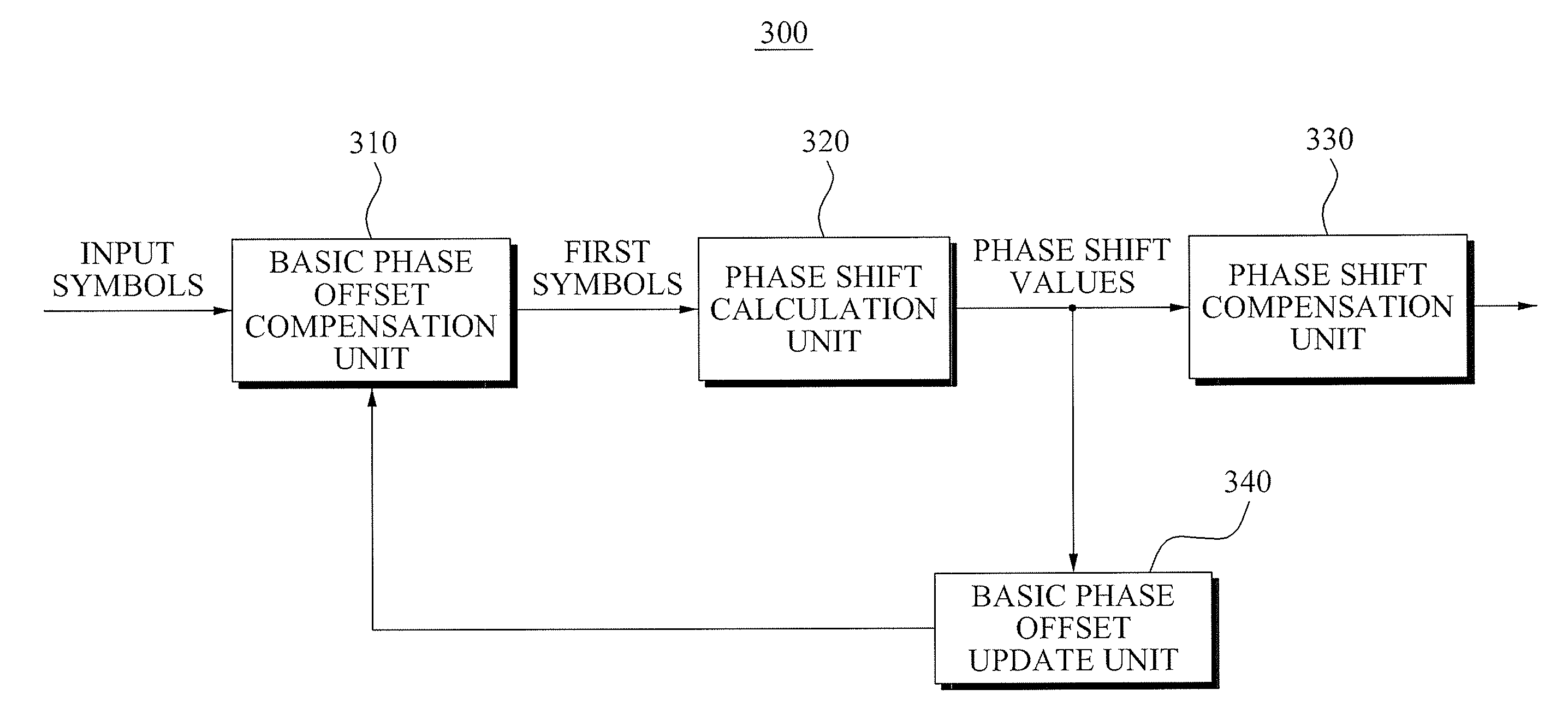
[0013]An aspect of the present invention provides a residual frequency offset compensation apparatus which updates a basic phase offset based on a phase shift value, and is applied to symbols generated according to a high order Quadrature Amplitude Modulation (QAM), and thereby may efficiently compensate a residual frequency offset.
[0014]Another aspect of the present invention also provides a residual frequency offset compensation apparatus which compensates a residual frequency offset using a basic phase offset which may be accumulatively increased, and thereby may efficiently compensate the residual frequency offset even when a length of data portion increase.
[0015]Another aspect of the present invention also provides a residual frequency offset compensation apparatus which may compensate a residual frequency offset without decreasing a data transmission rate.

Problems solved by technology

However, although symbols included in a preamble portion are used, a timing offset, frequency offset, and phase offset may not be completely compensated due to noise and frequently changed channel state.
In particular, symbols included in a data portion has a phase shift due to a residual frequency offset generated since a frequency offset may not be accurately estimated and compensated.
Also, the first and second method may not be applied to symbols generated according to a High Order Quadrature Amplitude Modulation (QAM), since the symbols are significantly affected by a residual frequency offset.

Method used


Image

  • Residual frequency offset compensation apparatus using phase shift compensation scheme
  • Residual frequency offset compensation apparatus using phase shift compensation scheme
  • Residual frequency offset compensation apparatus using phase shift compensation scheme

Examples


Embodiment Construction

[0024]Reference will now be made in detail to exemplary embodiments of the present invention, examples of which are illustrated in the accompanying drawings, wherein like reference numerals refer to the like elements throughout. The exemplary embodiments are described below in order to explain the present invention by referring to the figures.

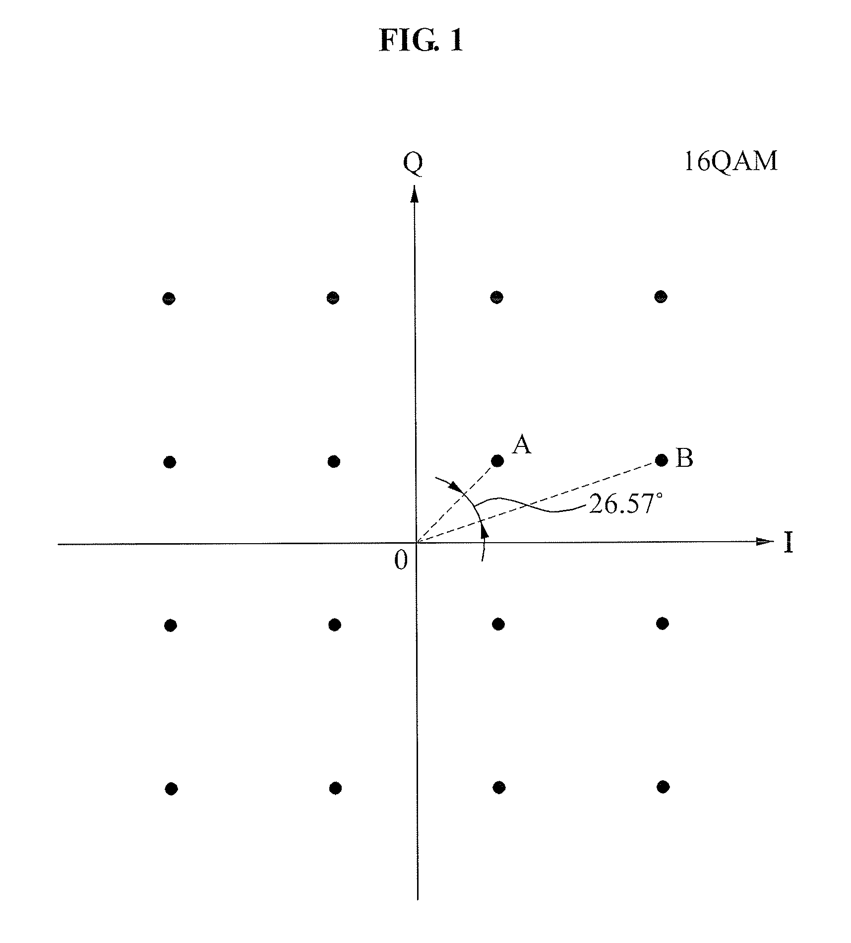
[0025]FIG. 1 is a diagram illustrating symbols modulated according to a 16 Quadrature Amplitude Modulation (QAM) according to an embodiment of the present invention.

[0026]Referring to FIG. 1, 16 points indicate symbols which may be modulated and generated according to the 16 QAM. According to the 16 QAM, four-bit data is mapped to any one of the 16 symbols and modulated.

[0027]When a residual frequency offset exists, a phase of symbols detected by a receiving end is different from a phase of symbols modulated by a transmitting end due to the residual frequency offset, even though the transmitting end transmits symbols modulated according to the ...


PUM


Abstract

A residual frequency offset compensation apparatus is provided. The residual frequency offset compensation apparatus includes: a basic phase offset compensation unit compensating input symbols using a previously stored basic phase offset and generating first symbols; a phase shift calculation unit calculating a phase shift value of each of a predetermined number of the first symbols using first detection symbols and the first symbols, the first detection symbols being generated by detecting the first symbols; a phase shift compensation unit compensating the first symbols based on an average of the phase shift values; and a basic phase offset update unit updating the basic phase offset based on the phase shift values.

Description

CROSS-REFERENCE TO RELATED APPLICATION[0001]This application claims priority from Korean Patent Application No. 10-2007-0129685, filed on Dec. 13, 2007, in the Korean Intellectual Property Office, the entire disclosure of which is incorporated herein by reference.BACKGROUND OF THE INVENTION[0002]1. Field of the Invention[0003]The present invention relates to a technology compensating a signal received in a receiving end in a communication system, and more particularly, to a technology compensating a residual frequency offset.[0004]This work was supported by the IT R&D program of MIC / IITA. [2006-S-019-02, The Development of Digital Cable Transmission and Receive System for 1 Gbps Downstream][0005]2. Description of Related Art[0006]In general communication systems, a transmitting end transmits a signal divided into a preamble portion and data portion. A preamble portion includes a preamble used for synchronization, and a data portion includes information to be actually transmitted.[00...

Claims


Application Information

Patent Timeline
IPC IPC(8): H04L27/06
CPCH04L27/0014H04L2027/0067H04L27/34
Inventor JIN, EUN SOOKSONG, YUN JEONGLEE, SOO IN
Owner ELECTRONICS & TELECOMM RES INST
Learn More